113
AX
AW
F
AJ
AJ
X
AK
S
Fig. 9.39
Fig. 9.42
R
P
K
K
J
T
K
U
Fig. 9.40
Fig. 9.41
Tab. 9.18
ED0053030410
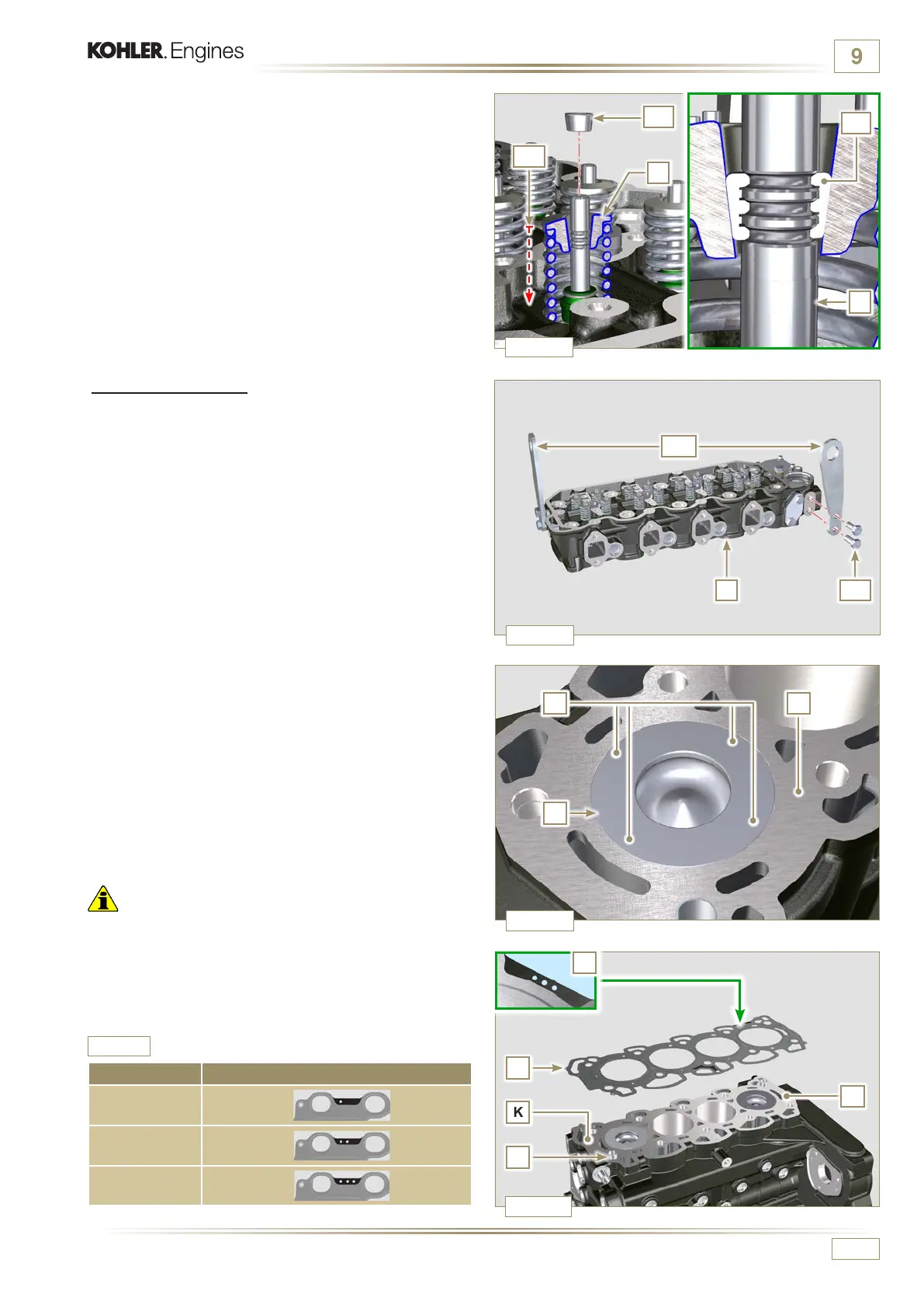
ASSEMBLY INFORMATION
9.5.5 Cylinder head
1 - Fix the eyebolts AW with the screws AX onto the head F
(tightening torque of 80 Nm).
6 -
Push the lever of the tool ST_07 downwards, in order to
lower the valve disks S in the direction of the arrow AK,
and insert the valve cotters AJ inside the disk S.
7 - Check that the valve cotters AJ are properly mounted on
the valve seats X and release the tool ST_07.
NOTE:
repeat all the steps for the relevant valves and remove
the tool ST_07.
2 - Position the piston P at the TDC.
3 - Position the tool ST_03 on the crankcase surface of the
head and measure the piston protrusion P from head level
K in 4 diametrically opposed points R.
Repeat the operation for all pistons P and take note of the
highest average value, determining value S (Tab. 9.4).
4 - Based on the value detected at point 3, select the relevant
gasket T as shown in the Tab. 9.4 (Fig. 9.42 detail U).
5 - Check that the crankcase surface K and the gasket T are
completely free of dirt and grit.
Important
• The head gasket must be replaced for each assembly.
6 - Position the gasket T on the surface K with reference to the
centering bushings J.
S (mm) Hole number
0.030 - 0.126
1
0.127 - 0.250
2
0.251 - 0.375
3

 Loading...


