114
5
4
7
V
8
1
2
3 9
6 10
Fig. 9.46
Fig. 9.45
F
W
Z
J
J
Fig. 9.43
Fig. 9.44
AC AC
AB
F
AA
Tab. 9.19
ED0053030410
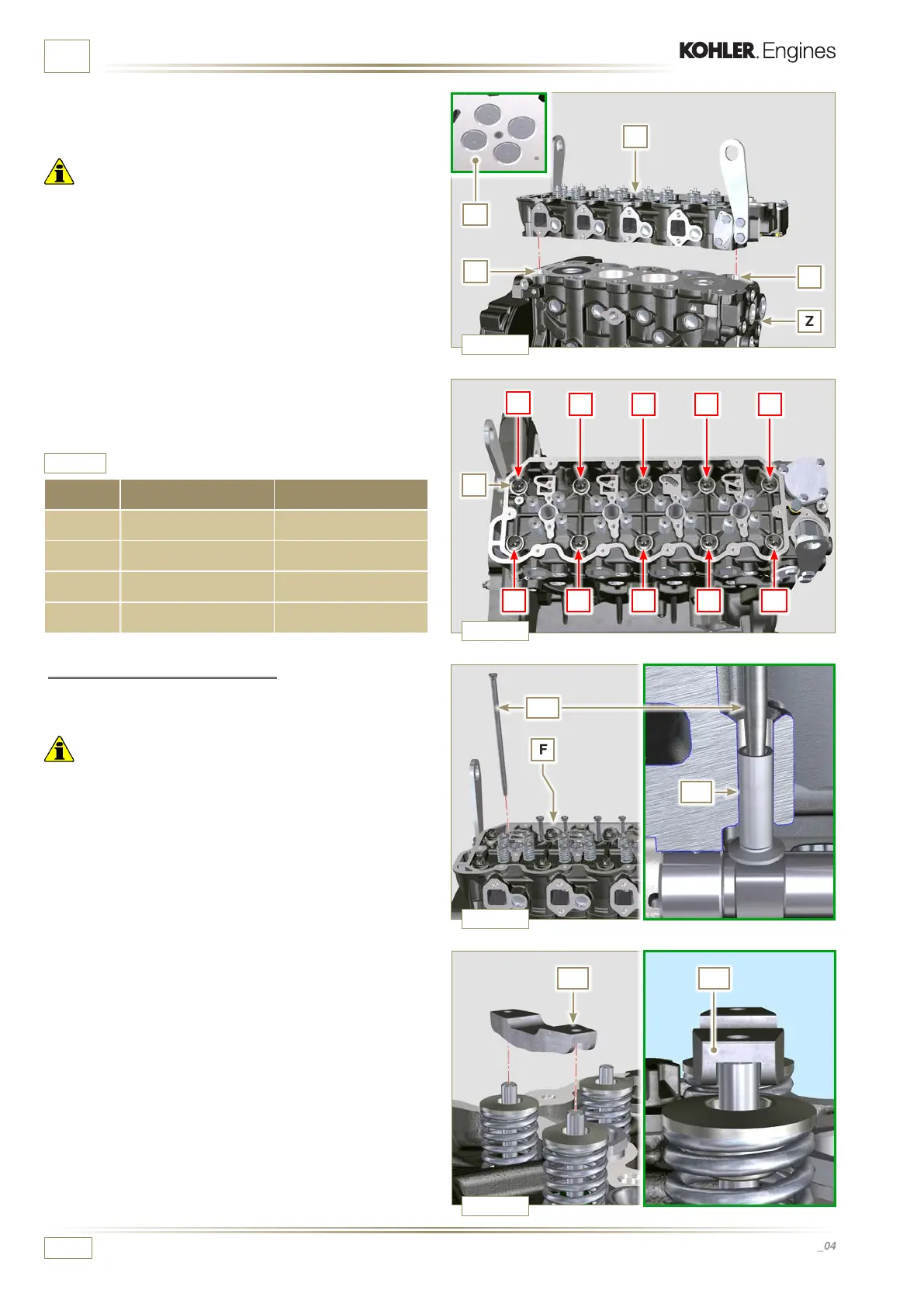
ASSEMBLY INFORMATION
7 - Check that the surface head W is free from impurities.
8 -
Position the head F on the crankcase Z with reference to
the centering bushings J.
Important
• The fastening bolts V must be replaced every time they are
assembled.
• Failure to adhere to the bolt fixing procedures may
compromise the functionality of the engine, and also may
cause damage to persons and property.
• Tighten capscrews V observing the cycles, tightening, and
subsequent rotation as indicated in Tab. 9.5.
9 -
Apply "Molyslip AS COMPOUND 40" on the threads and
under the head of capscrew V and manually tighten them
until their stop.
10 -
Secure the head F by tightening the screws V strictly
following the sequence indicated in the Fig. 9.44 and the
tightening torque and pauses between cycles indicated in
the Tab. 9.5.
CYCLE TORQUE PAUSE
1 28 Nm 3"
2 30° 3"
3 30° 10"
3 30° ...
2 - Mount the valve bridge AC on to the pairs of discharge and
suction valves.
9.5.6 Rods and valve bridges
1 - Insert the rocker control rods AA into the niches of the
head F.
Important
• Properly centre the rods AA into the spherical housing of the
camshaft tappets AB.

 Loading...


