115
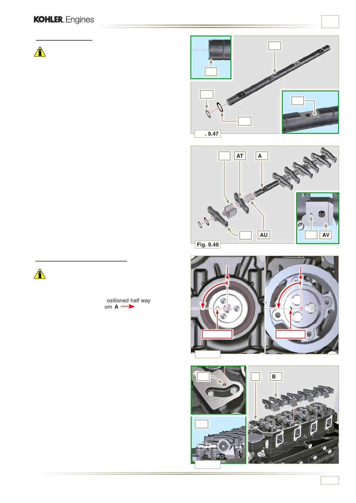
Fig. 9.47
BBBF F
BD
Fig. 9.48
AN
AP
Fig. 9.50
AU AVBC
AH
AR
AT
AS
AM
AH
AQ
BP = -90° BP = -90°
Fig. 9.49
ED0053030410
ASSEMBLY INFORMATION
9.5.8 Rocker arm pin assembly
Important
• Position the rocker arm pin assembly BB on a level to align
all the support surfaces.
• Check that the pistons are positioned half way between the
TDC and BDC. As seen from A (Par. 1.4) turn the
crankshaft anticlockwise by 90°, complying with TDC of the
1st cylinder, positioning taper pin BP of the crankshaft as
shown in Fig. 9.49.
1 - Position rocker arm shaft unit BB on cylinder head F,
complying with the taper pin BC reference with hole BF of
cylinder head F.
2 -
Check the correct positioning of all the rocker arms and the
u-bolt control valves (detail BD).
House the tappet in the seat of the rocker arms control rod.
9.5.7 Rocker arms
Important
• The suction rocker arm AT is shorter than the discharge arm
AR.
1 -
Fit the lock ring AM into the seat AN of the rocker arm pin
AH.
2 - Position the pin AH with the surface AP facing upwards
and insert the 2 shoulder rings AQ.
3 - Insert in sequence the suction rocker arm AR, the holder
AS and the discharge rocker arm AT in the pin AH.
4 - Insert the spring AU in the pin AH.
5 -
Repeat points 3, 4 for all the rocker arms.
NOTE:
Support AV, which contains taper pin BV, must be
assembled in correspondence with cylinder n° 3.
6 - Insert 2 shoulder rings AQ and the lock ring AN to lock all
the components inserted in the pin AH.
NOTE:
The spring AU ensures that the supports AS and AV
are kept in place .

 Loading...


