116
BB
BE
12 3
4
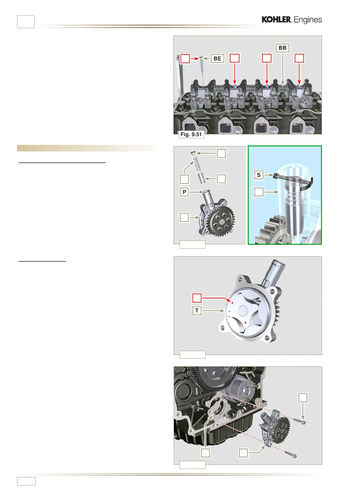
Fig. 9.51
R
N
P
T
T
V T
X
U
Q
S
S
Fig. 9.52
Fig. 9.53
Fig. 9.54
ED0053030410
ASSEMBLY INFORMATION
3 - Secure the rocker arm pin BB tightening the screws
BE (tightening torque to 40 Nm). Adhere to the screw
tightening sequence BE as shown in Fig. 9.51.
9.6 Assembly lubrication circuit
9.6.1 Oil pressure relief valve
1 - Lubricate the piston N and fully insert it in the seat P.
2 - Insert the spring Q in the piston N.
3 - Insert disk R onto spring Q.
4 - Insert cotter pin S in the provided seat of oil pump T to lock
components N, Q, and R.
9.6.2 Oil pump
NOTE: Carry out the checks described in Par. 8.7 before
proceeding with the following operations.
1 - Check that all contact surfaces between T, V are free of
impurities – scratches - dents.
2 - When assembling, do not use any type of gasket between
T and V.
3 - Thoroughly lubricate the seat of the rotors on oil pump T.
4 - Make sure the external rotor is assembled correctly with
Ref. U visible, as shown in the picture (or refer to Par.
2.10.2).
5 - Fasten the oil pump cover T on the crankcase V with the
screws X (tightening torque 10 Nm).

 Loading...


