117
C
E
E
D
G
G
F
F
B
A
AF
1
13
12
14
15
161723
4
5
6
7
8 10
9
11 18
G
L
G
ST_41
H
LOCTITE 5660
Fig. 9.55
Fig. 9.56
Fig. 9.57
ED0053030410
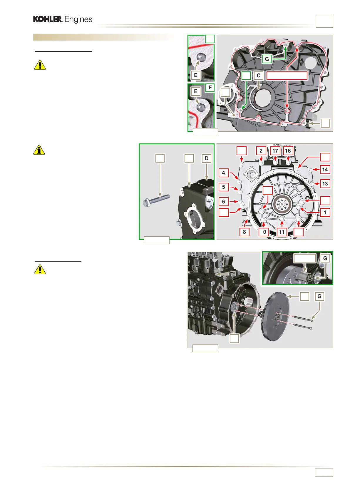
ASSEMBLY INFORMATION
9.7 Flange unit assembly
9.7.1 Bell housing
Danger
• Bell A is very heavy; pay special attention during assembly
operations to avoid dropping and causing serious risks to
the operator.
1 - Apply a bead of approx. 2.5 mm of sealant (Loctite 5660)
on the surface B of the bell A.
2 - Assemble bell A onto crankcase D, complying with
reference taper pins E (ST_45).
9.7.2 Flywheel
Danger
• Flywheel H is very heavy; pay special attention during
assembly operations to avoid dropping and causing serious
risks to the operator.
1 - Loosen capscrews G and remove tool ST_41.
2 - Position flywheel H onto crankshaft L by means of tool
ST_43 - ST_46.
3 - Apply "Molyslip AS COMPOUND 40" on the threads and
under the head of capscrews G and manually tighten them
until their stop.
4 - Secure flywheel H with capscrews G (tightening torque 60
Nm).
5 - Once again, tighten capscrews G (2 cycles with tightening
torque 130 Nm).
Important
• Failure to adhere to the assembly
procedures may compromise the
functionality of the engine, and also
cause damage to persons and property.
• Always replace and lubricate the gasket
C wit h o i l, eve r y t i m e t h ey are a s sembled
(the gasket C is to be mounted after the
operation at point 4, ST_47).
3 -
Apply the screws F by hand without
tightening them.
4
- Tighten the screws F following
the tightening sequence indicated
(tightening torque 75 Nm).

 Loading...


