118
A
ACD B
B
Fig. 9.58
Fig. 9.59
ED0053030410
ASSEMBLY INFORMATION
9.8 Fuel system assembly
Important
• Remove the protective caps from all the components of the
fuel circuit just before assembly just before assembly (Par.
2.9.8).
9.8.1 High-pressure injection pump
1 - Follow operations 1, 2, 3, 4, 5, 6, 7 and 8 of Par. 6.1.5.
2 - Follow operations 1, 2, 3, 4, 5, 6, 7 and 10 of Par. 6.1.6.
9.8.6 Fuel lter
1 - Perform the operations of Par. 6.5.2.
9.8.2 Injectors
Important
• To prevent damaging the injection system, the protection caps
(Par. 2.9.7) must be removed during assembly.
1 - Follow operations of Par. 6.1.7.
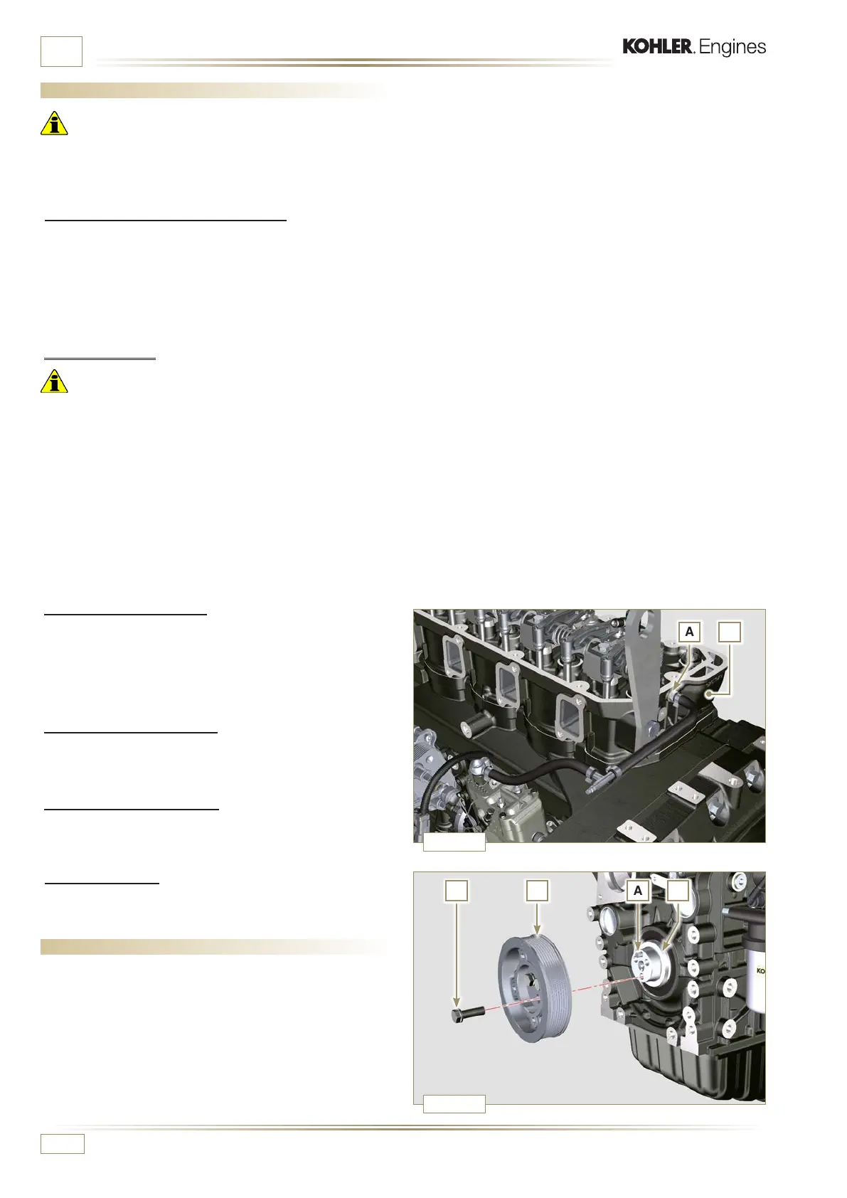
9.8.3 Fuel return pipes
1 - Tighten union A onto cylinder head B, inserting the relative
gasket.
2 - Perform the operations of point 18 of Par. 6.1.5.
9.8.4 Rocker arms cover
1 - Perform the operations of Par. 6.1.9.
9.8.5 Injection fuel pipes
1 - Perform the operations of Par. 6.1.10.
9.9 Crankshaft pulley assembly
1 -
Check that the pin A is mounted properly on the crankshaft
B.
2 -
Position the pulley C on the crankshaft B using the pin
mark A.
3 -
Apply "Molyslip AS COMPOUND 40" grease onto the
thread and under the head of capscrew D.
4 -
Fix the pulley C with the screw D (tightening torque of 100
Nm) and remove special tool ST_34.

 Loading...


