134
A
A1
A2
A
D
B B
Fig. 12.4
Fig. 12.5
A C
B
C
Fig. 12.2
Fig. 12.3
ED0053030410
INFORMATION ON ADJUSTMENTS
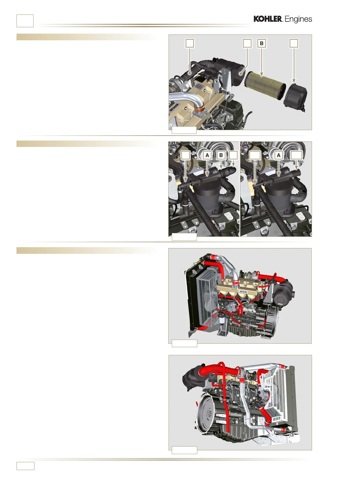
12.3 Oil steam separator check
1 -
Loosen clamp B and remove hose C from separator A.
2 - Remove rapid fitting D from separator A.
3 - Start the engine at idle speed or without a load and check
if air comes out from unions A1 and A2.
NOTE: If what is described in Point 3 does not occur, proceed
with cleaning or replacing oil separator A and all
connecting hoses. Repeat the operation from point 3.
12.4 Rubber hoses and manifolds check
The check is carried out by applying slight deection or
bending along the tube/hose and next to the hose clamps.
C o m p o n e n t s m u s t b e r e p l a c e d i f t h ey h a v e c l e a r s i g n s o f c r a c k s ,
tears, cuts, leaks, or do not retain a certain degree of elasticity.
1 -
Check the condition of all hoses and rubber tubes
highlighted in red in Fig. 12.4 - 12.5.
2 - Check whether there are any leakages of air, coolant, oil or
fuel next to their connections.
NOTE: Refer to the technical documentation of the machine
for components that are not shown in the gure.
12.2 Air lter check
1 -
Hose A must be completely clean and not damaged.
2 - Air filter cartridge B and its housing C must be completely
clean and free from impurities.

 Loading...


