14
1
A
B
4
5
6
7
89
15
10
23
Fig. 1.5
Tab. 1.2
ED0053030410
GENERAL INFORMATION
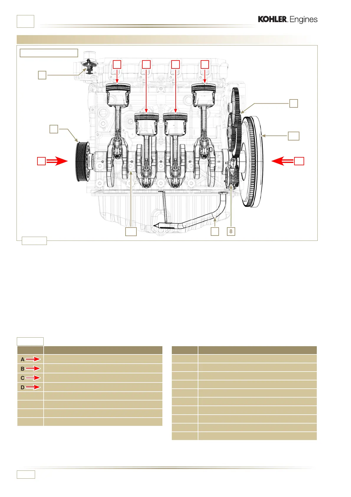
1.4 Identication of the main internal components of the engine and operating reference (BASE CONFIGURATION)
REF. DESCRIPTION
A
View of crankshaft pulley (2
nd
PTO)
B
View of ywheel side (1
st
PTO)
C
View of exhaust side
D
View of intake side
1 Cylinder/Piston N. 1
2 Cylinder/Piston N. 2
3 Cylinder/Piston N. 3
4 Cylinder/Piston N. 4
VIEW OF INTAKE SIDE
The following chapters contain operating references in order
to clearly understand the engine. This paragraph illustrates
these references that may be recognised by means of some
main internal components.
Should you need to execute complex operations, always
consult this paragraph.
NOTE: it is advisable to keepthis page visible during disassembly
and assembly operations.
POS. DESCRIPTION
5 Crankshaft pulley (2
nd
PTO)
6 Gear timing system
7 Thermostatic valve
8 Oil pump
9 Oil suction hose
10 Crankshaft
11 Exhaust manifold
12 Intake manifold
13 Camshaft
14 Flywheel (1
st
PTO)
 Loading...


