33
1
2
6
17
7
7
6
12
4
3
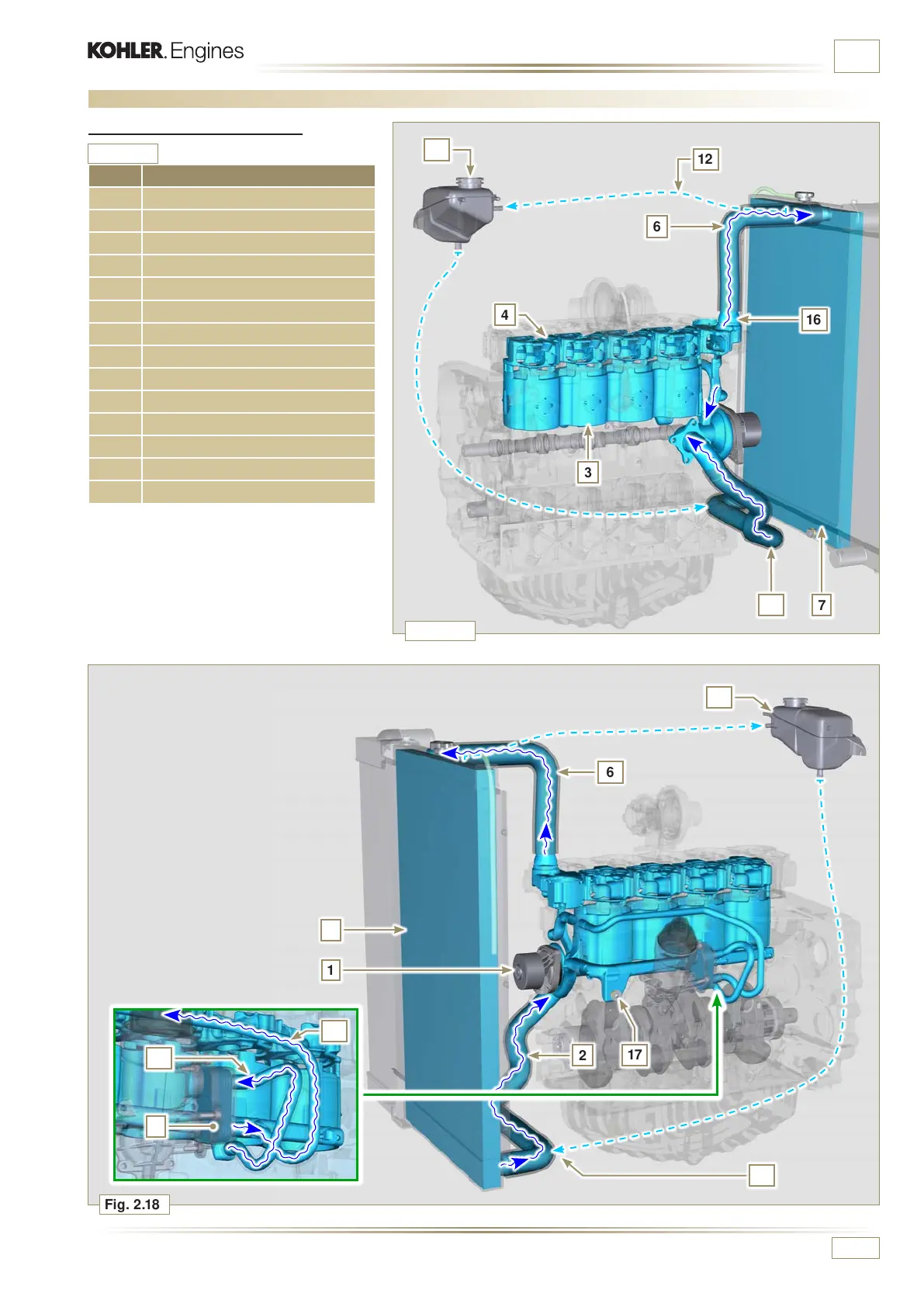
Fig. 2.17
Fig. 2.18
16
15
15
Tab. 2.23
9
10
11
14
14
ED0053030410
TECHNICAL INFORMATION
POS. DESCRIPTION
1 Coolant pump
2 Coolant intake
3 Coolant, cylinder
4 Coolant, cylinder head
6 Coolant to radiator
7 Coolant into radiator
9 Coolant in the Oil Cooler
10 Coolant input into the Oil Cooler
11 Coolant output from the Oil Cooler
12 Vent line from radiator (to 15)
14 Return from compensation tank
15 Compensation tank
16 Thermostatic valve
17 Coolant drain cap from crankcase
2.11 Coolant circuit
2.11.1 Coolant circuit diagram

 Loading...


