79
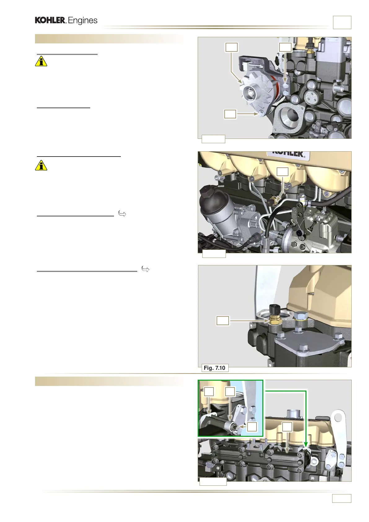
B1
A1
C1
Fig. 7.10
Fig. 7.9
Fig. 7.8
Fig. 7.11
G1
F1
D
CE
B
ED0053030410
INFORMATION FOR DISASSEMBLY
7.4 Electric components disassembly
7.4.1 Starter motor
Important
• The motor is not repairable.
1 - Perform the operations from point 2 to 3 of Par. 6.1.5.
7.4.2 Alternator
1 - Undo the screws A1 and B1 and remove the alternator C1.
7.4.3.2 Coolant temperature sensor ( )
1 - Unscrew and remove the coolant temperature sensor G1.
7.4.3 Sensors and switches
Important
• After disassembly, protect the sensors suitably against
knocks, dampness and any high temperature sources.
• The sensors and switches cannot be repaired, therefore they
must be replaced in the event of anomalies.
7.4.3.1 Oil pressure switch ( )
1 - Unscrew and remove the oil pressure switch F1.
7.5 Exhaust manifold disassembly
1 -
Remove capscrews B and spacers C, manifold D and
gaskets E.
2 - Close the openings and manifolds to prevent foreign bodies
from entering.

 Loading...


