96
Fig. 8.8
B
C
F
D
Q
R
T
S
P
Fig. 8.10
A
E
E
Fig. 8.11
D
Tab. 8.6
Fig. 8.9
ED0053030410
INFORMATION ABOUT OVERHAULING
8.5 Connecting rod - piston assembly
8.5.1 Connecting rod dimensions check
Important
• Before assembling the connecting rod and pistons (Par. 9.3.7
and 9.3.8), check that the difference in weight between the
complete connecting rod and piston units do not exceed 15 gr
to prevent weight imbalances during rotation of the crankshaft
and consequent damage.
• Mark some references on the connecting rods, caps Q, pistons
and gudgeon pins to prevent unintentionally confusing the
components during assembly. Failure to do this may result in
engine malfunctions..
• Connecting rod half-bearings S must be replaced at each
assembly.
Check that the contact surfaces are perfectly clean and intact.
Assemble the connecting rod cap Q to the connecting rod with
the half-bearings S and tighten capscrews P (tightening torque
at 28 Nm).
With a dial gauge, measure diameters B and D.
The MAX allowed value of wear for B and D is 0.06 mm.
Important
• Tab. 8.6 details the dimensional values of new components
only.
• Check that the connecting rod and crankshaft half-bearings
are coupled properly.
• Refer to the warnings in Par. 8.4.1 for value D decreased.
• If the clearance value between B and D is not observed, you
are required to replace bearing R (Fig. 8.10).
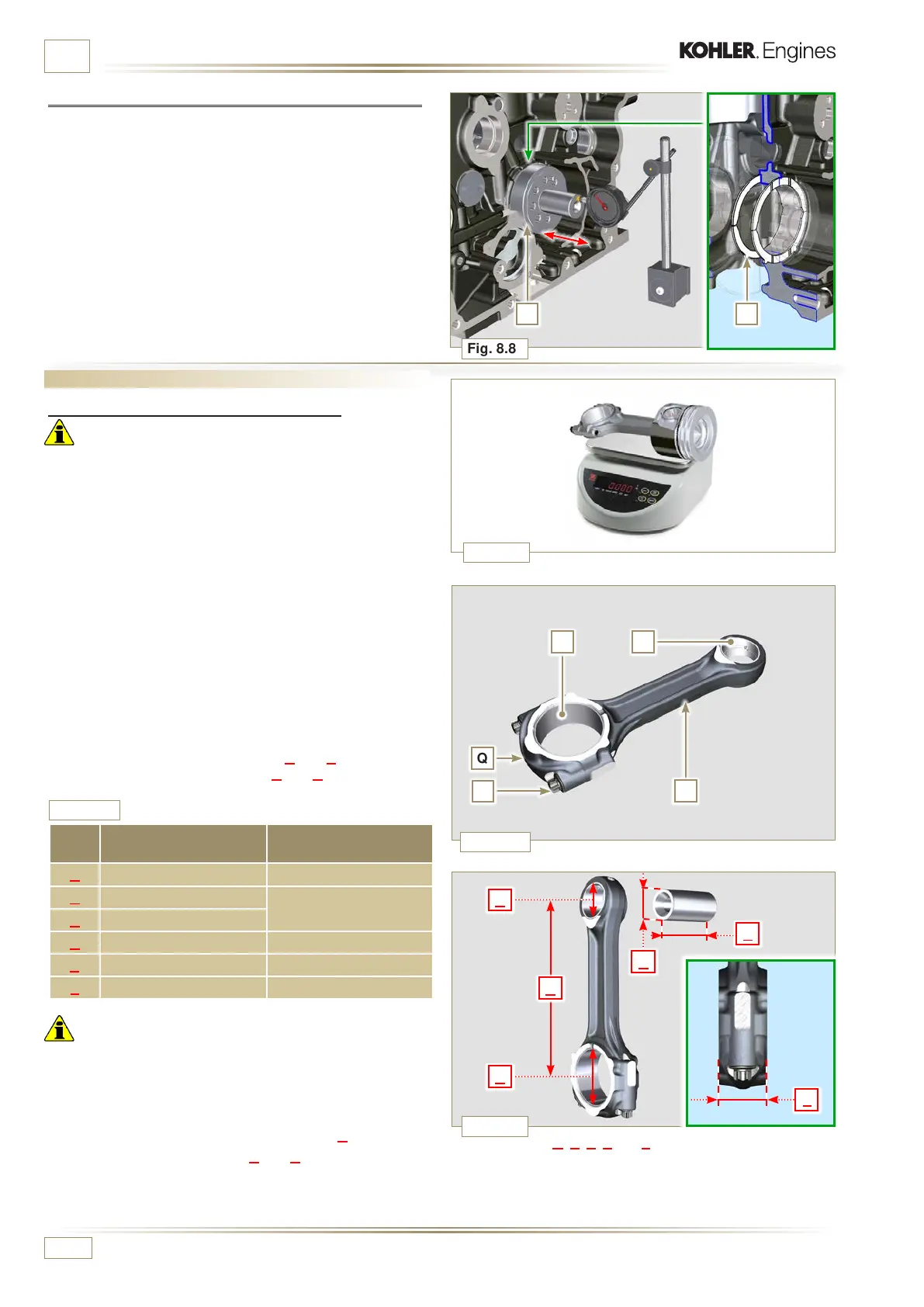
8.4.2 Checking the axial clearance of the crankshaft
Perform the operations described in P a r. 9.3 .1, 9.3.4 and. Par.
9.3.5 - except points 2, 3, 5, and 10.
Tighten capscrew J (Fig. 9.9) observing the cycles, tightening,
and subsequent rotation.
Cycle 3 - Screw J - Torx M14x1,5 - Torque 45°. (Fig. 9.9)
Cycle 4 - Screw J - Torx M14x1,5 - Torque 45°. (Fig. 9.9)
Using a dial gauge, measure the axial shift of crankshaft E.
Axial shift must be a MIN of 0.18 mm and MAX 0.38 mm..
If the values measured do not correspond, replace shoulder
rings D.
Measure value A, C, D, E and F and confront them with those
described in Tab. 8.6.
If the measured values do not follow those described in Tab.
8.6, replace connecting rod T.
REF. DIMENSIONS (mm)
CLEARANCE
VALUE (mm)
A 192.980 - 193.020
B 37.0 25 - 37.015
0.015 - 0.030
C 36.995 - 37.000
D 61.034 - 61.069
E 74.000 - 74.300
F 33.950 - 33.990

 Loading...


