7
107
_07
Fig. 7.61
S
U
T
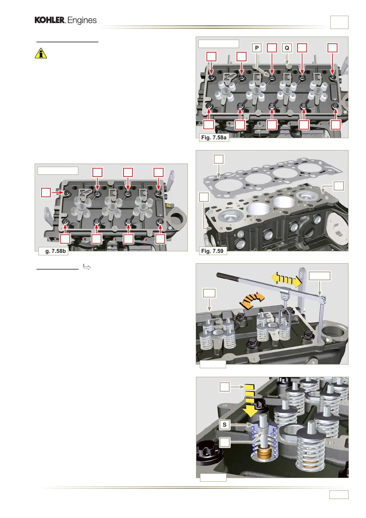
Fig. 7.59
R
J
W
Fig. 7.60
AF
Fig. 7.58a
Fig. 7.58b
P Q
ST_07
1
2
5
4
3
6
7
8
5
4
7
8
1
2
3 9
6
10
ED0053029590
INFORMATION FOR DISASSEMBLY
7.13.4 Cylinder head
Important
• The cylinder head fastening bolts P must be replaced every
time they are disassembled.
• To lift cylinder head Q, only use both eyebolts AE provided
by KOHLER (refer to Fig. 7.66).
• When removing the cylinder head Q and subsequent
disassembly, control, and assembly operations, it is
necessary to protect the contact surface W of cylinder head
Q and crankcase J against impacts..
1 - Undo the bolts P by following the order indicated in the
figure.
2 - Remove the cylinder head Q.
3 - Remove the head gasket R.
7.13.4.1 Valves ( )
1 - Mount the tool ST_07 on the head AF fixing it on one of the
holes for fixing the rocker arm cover.
NOTE:
Change the xing hole according to the position of the
valves to be removed.
2 -
Position the tool ST_07 on the valve as shown in the figure.
3 -
Push the lever of the tool ST_07 downwards, in order to
lower the valve plates S in the direction of the arrow T,
remove cotters U using a magnet.
NOTE:
Repeat all the operations for all the valves concerned.
3 CYLINDERS
4 CYLINDERS

 Loading...


