7
111
_07
Fig. 7.71
M
L
AK
Fig. 7.72
L
Z
M
Fig. 7.73
1
8
3
4
6
2
5
7
14
15
13
16
12
17
11
18
10
19
21
20
9
D
D
E
F
ED0053029590
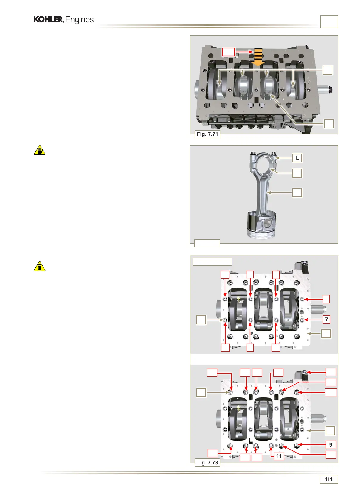
INFORMATION FOR DISASSEMBLY
7.15.3 Lower semi-crankcase
Important
• The fastening bolts E, F must be replaced every time they
are disassembled.
3 CYLINDERS
1 -
Undo capscrews E and F by following the order indicated
in the figure.
2 -
Remove the lower semi-crankcase D and store it in a
suitable container for washing.
3 CYLINDERS
Warning
• The connecting rod half-bearings Z are made of special
material. Therefore, they must be replaced every time they
are removed to prevent seizures.
3 - Pull out the connecting rod - piston assembly from position
2 and 3 by manually applying pressure on the connecting
rod M in the direction of arrow AK.
4 - Couple the connecting rod big end caps L with the relevant
piston and connecting rod unit M.
5 - Turn capscrew AM and rotate the crankshaft by 180°.
6 - Repeat points 2 to 5 to disassemble the connecting rod -
piston assembly to position 1 and 4.

 Loading...


