7
110
_07
Fig. 7.69
A B
C
Fig. 7.70
1 2 3 4
AM
Fig. 7.70b
Fig. 7.70c
Fig. 7.70a
M
E1
K1
K2
F1
ED0053029590
INFORMATION FOR DISASSEMBLY
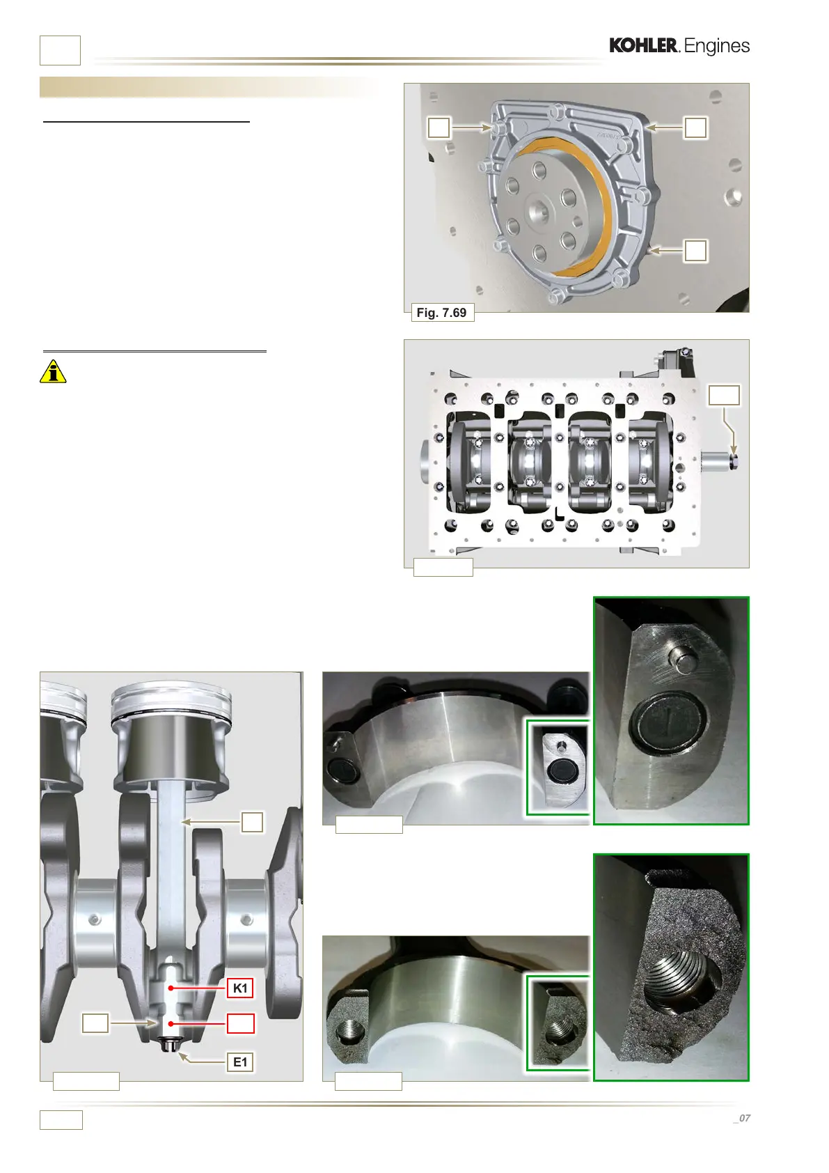
7.15 Engine block disassembly
7.15.1 Crankshaft gasket ange
1 - Undo the screws A.
2 -
Remove the flange B and the gasket C.
7.15.2 Piston unit / connecting rod
Important
• Mark some numerical references (cylinder n°) on the
connecting rods, connecting rod caps F1, pistons and gudgeon
pins to prevent unintentionally confusing the components not
replaced during assembly. Failure to do this may result in
engine malfunctions.
• References on connecting rod M and cap F1 must only be
carried out on a side in correspondence with K1 and K2 , as
illustrated in Fig. 7.70a.
1 - Screw the bolt AM temporarily.
2 - Unsrew bolts E1 and remove the connecting rod caps F1.
NOTE: coupling cap F1 on the connecting rod can be carried
out with centring taper pins (Fig. 7.70b) or broken
(Fig. 7.70c - without centring taper pins).

 Loading...


