7
112
_07
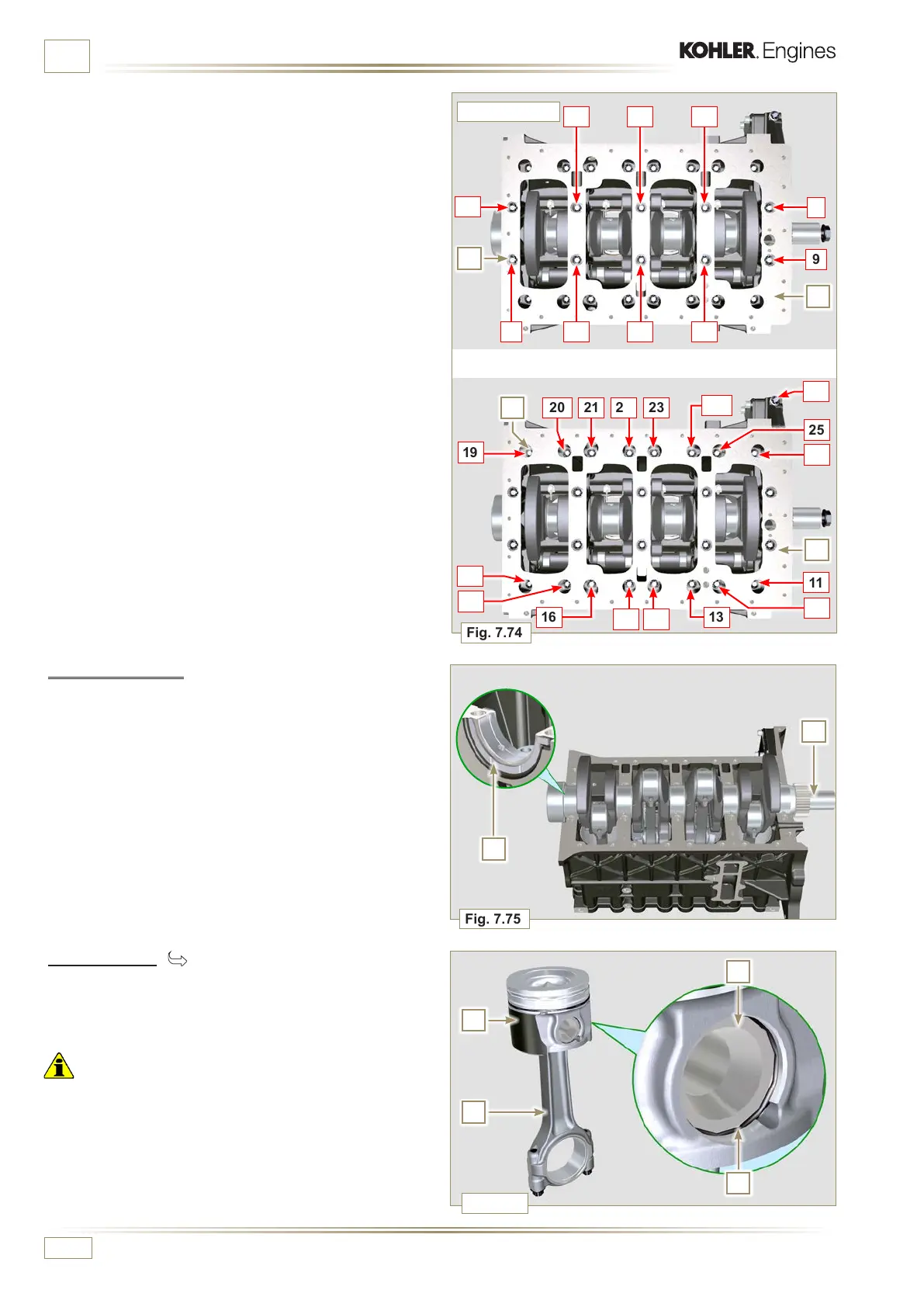
Fig. 7.75
G
H
Fig. 7.76
N
P
Q
R
Fig. 7.74
1
7
3 5
26 4
9
10
8
21
23
25
11
22
24
16
1415
13
12
26
27
20
18
17
19
D
D
E
F
ED0053029590
INFORMATION FOR DISASSEMBLY
7.15.4 Crankshaft
Remove:
1 - Crankshaft G.
2 - The shoulder semi-rings H.
7.15.5 Piston ( )
1 - Remove the retainer ring N.
2 - Remove the pin P to separate the piston Q from the
connecting rod R.
Important
• If they are not replaced, keep the components together
(connecting rod - piston - gudgeon pin) by using references in
order to prevent them from get ting mixed up during assembly.
4 CYLINDERS
1 -
Undo capscrews E and F by following the order indicated
in the figure.
2 - Remove the lower semi-crankcase D and store it in a
suitable container for washing.
4 CYLINDERS

 Loading...


