122
8
_07
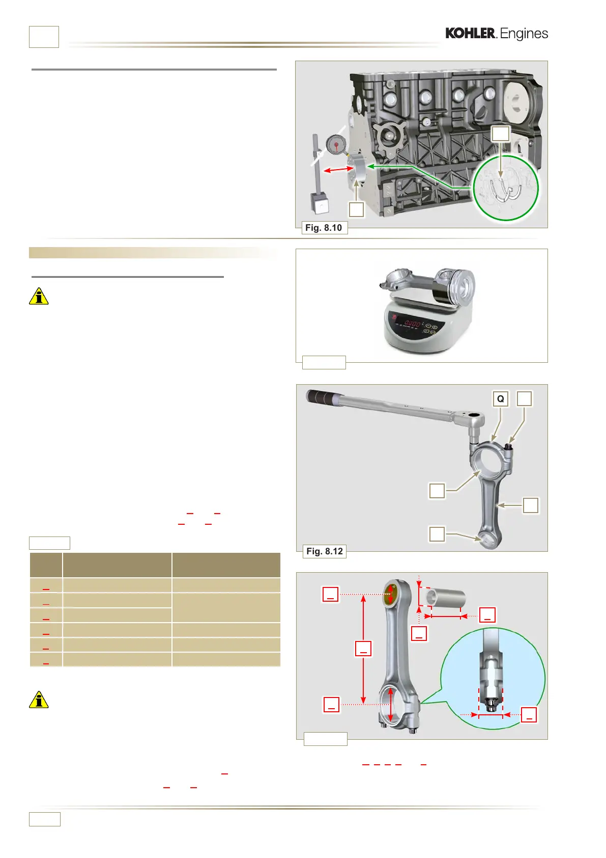
Fig. 8.12
Fig. 8.13
B
C
F
D
Q
R
T
S
P
Fig. 8.10
A
E
D
E
Fig. 8.11
ED0053029590
INFORMATION ABOUT OVERHAULING
8.5 Connecting rod - piston assembly
8.5.1 Connecting rod dimensions check
Important
• Before assembling the c onnec ting ro d and pistons (Par. 9. 3.7
and 9.3.8), check that the difference in weight between the
complete connecting rod and piston units do not exceed 8 gr
to prevent weight imbalances during rotation of the crankshaft
and consequent damage.
• Mark some references on the connecting rods, caps Q, pistons
and gudgeon pins to prevent unintentionally confusing the
components during assembly. Failure to do this may result in
engine malfunctions..
• Connecting rod half-bearings S must be replaced at each
assembly.
Check that the contact surfaces are perfectly clean and intact.
Assemble the connecting rod cap Q to the connecting rod with
the half-bearings S and tighten capscrews P (tightening torque
at 25 Nm).
With a dial gauge, measure diameters B and D.
The MAX allowed value of wear for B and D is 0.06 mm.
Tab. 8.6
REF. DIMENSIONS (mm)
CLEARANCE
VALUE (mm)
A 169.980 - 170.020
B 30.020 - 30.030
0.025 - 0.030
C 29.995 - 30.000
D 54.035 - 54.066
E 67.70 0 - 68.000
F 29.750 - 29.790
Important
• Tab. 8.6 details the dimensional values of new components
only.
• Check that the connecting rod and crankshaft half-bearings
are coupled properly.
• Refer to the warnings in Par. 8.4.1 for value D decreased.
• If the clearance value between B and C is not observed, you
are required to replace bearing R (Fig. 8.12).
8.4.2 Checking the axial clearance of the crankshaft
Perform the operations described in Par. 9.3.5 e 9.3.6.
Using a dial gauge, measure the axial shift of crankshaft E.
Axial shift must be a MIN of 0.18 mm and MAX 0.38 mm..
If the values measured do not correspond, replace shoulder
rings D.
Measure value A, C, D, E and F and confront them with those
described in Tab. 8.6.
If the measured values do not follow those described in Tab.
8.6, replace connecting rod T.

 Loading...


