127
8
_07
Fig. 8.29
A
B
C
D
Fig. 8.28
Fig. 8.30
Fig. 8.31
G
H
LMN
ED0053029590
INFORMATION ABOUT OVERHAULING
8.7 Oil pump check
8.7.1 Dimensional and visual check
Perform the operations described in Par 7.8.1 and 7.8. 4.
Measure clearance value B between the rotor teeth, the value
of allowable wear is MAX 0.28 mm.
Clean all the components thoroughly, check that the work
surfaces C of the rotors and pump body are not worn.
Important
• Should the results from checks carried out not be in
accordance with the conditions described, replace the timing
system carter together with the oil pump.
On assembly, references A must be visible.
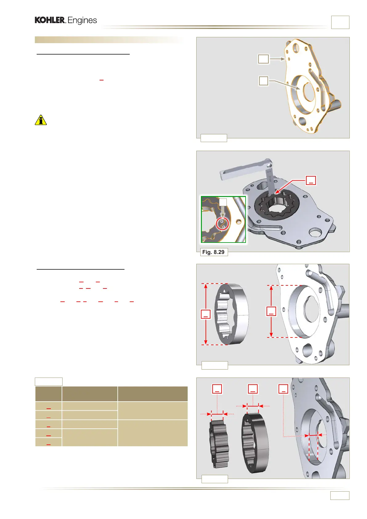
8.7.2 Rotors clearance check
Measure values G and H (Fig. 8.30).
Measure values L, M and N (Fig. 8.31).
According to the values measured, calculate the clearance
between G and H, L and M and L and N which are to observe
the values in Tab. 8.13.
For assembly, carry out the operations described from Par.
9.11.3 to Par. 9.11.4.
REF.
DIMENSIONS
(mm)
CLEARANCE VALUE
(mm)
G 82.820 - 82.855
0.032 - 0.075
H 82.500 - 82.540
L 15.500 - 15.525
0.036 - 0.086
M
15.464 - 15.489
N
Tab. 8.13

 Loading...


