9
140
_07
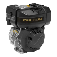
Fig. 9.38
Z
U
V
T
Fig. 9.40
AC
AE
Q
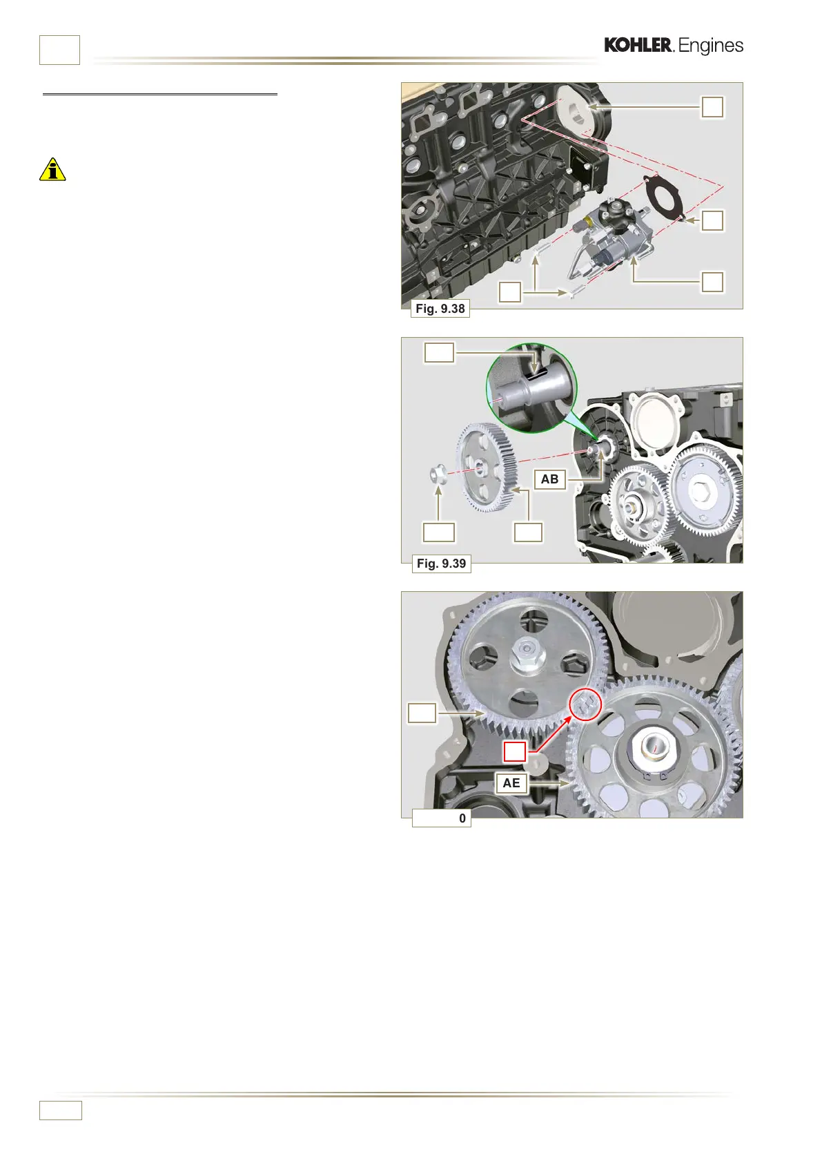
Fig. 9.39
AD
AB
AA
AC
ED0053029590
ASSEMBLY INFORMATION
9.6.2 High-pressure injection pump
1 - Check that the surface V is free from impurities (Fig. 9.38).
Important
• Always replace gasket U with every assembly.
• The seal gasket U can only be fitted in one direction (Fig. 9.38).
• Always replace capscrews T with new ones or alternatively
apply Loctite 2701 (Fig. 9.38).
2 - Fit the new gasket U on the injection pump Z (Fig. 9.38).
3 - Fix the pump Z into the housing V together with the gasket
U by the screws T (Fig. 9. 38 - tightening torque at 25 Nm).
4 - Check the correct fitting of the key AA on the shaft AB of
the injection pump (Fig. 9.39).
5 - Place the gear AC on the shaft AB of the pump respecting
the reference to the key AA and the reference Q of the
gear AE (Fig. 9.39).
Tighten the bolt AD (tightening torque at 65 Nm).
6 - Remove special tool ST_34.

 Loading...