9
139
_07
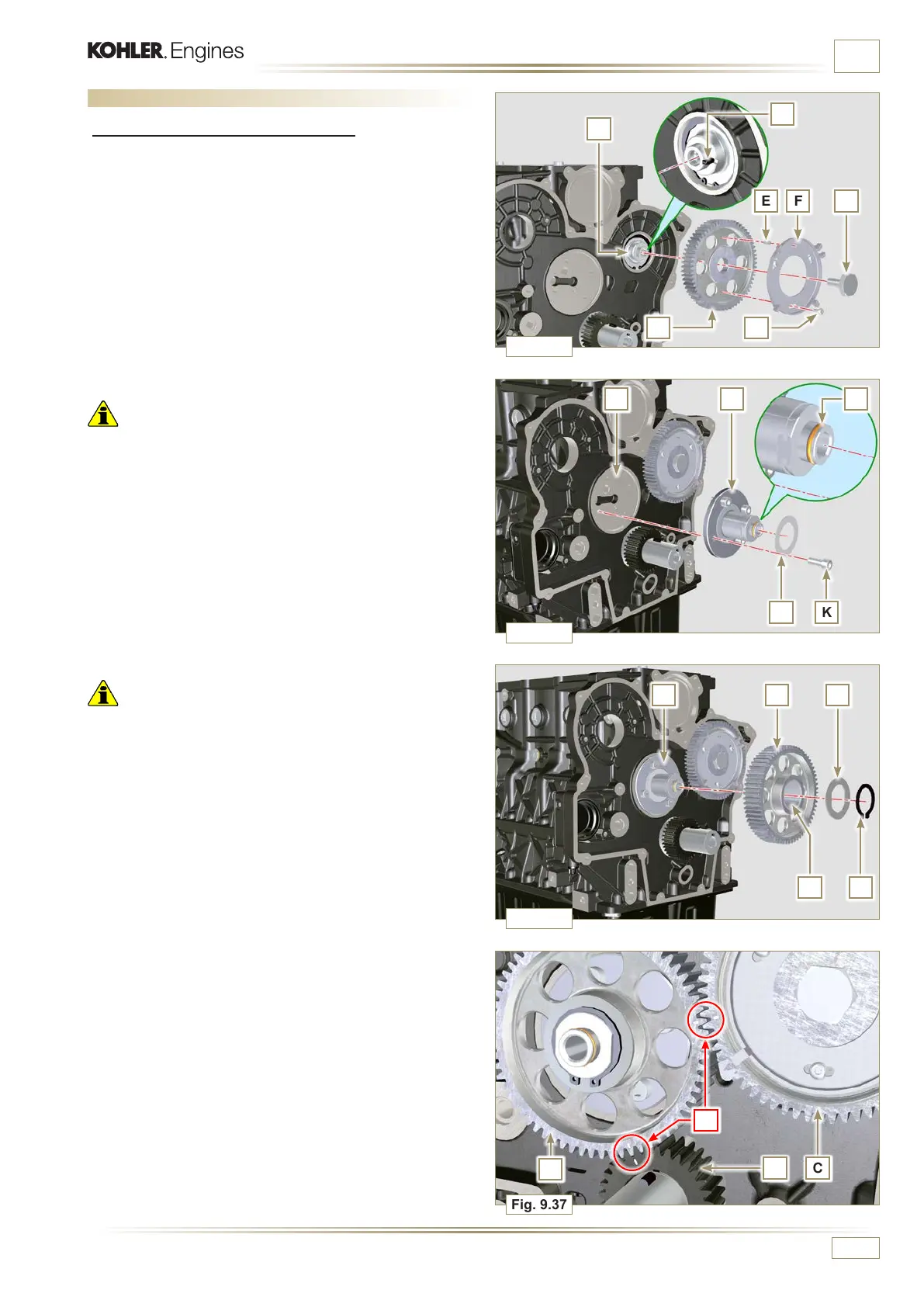
Fig. 9.37
P
CS
W
Fig. 9.36
PH Q
RN
Fig. 9.35
H LJ
KM
Fig. 9.34
A
E F D
C
B
G
ED0053029590
ASSEMBLY INFORMATION
9.6 Timing system gear assembly and injection pump
9.6.1 Timing system gear assembly
1 - Check that the key A is correctly fitted on the camshaft B.
2 - Position the gear C on the camshaft B adhering to the key
reference A.
3 - Screw capscrew D until the end.
4 - Insert the reference pin E on the gear C.
5 - Screw the encoder F with the screws G on the gear C
observing the plug E.
6 - Tighten the middle gear pin H, in the housing J of the
crankcase, with the screws K (tightening torque 25 Nm).
Important
• The fitting of the middle gear pin H has only one position, the
4 screw holes K are not equally spaced.
• Always replace the gasket L after each assembly.
7 - Insert the shoulder ring M.
8 - Check the integrity of the bushing N on the middle gear P,
and ensure that it is free from impurities.
9 - Thoroughly lubricate the pin H and the bushing N.
10 - Position the gear P on the pin H observing all the marks W
of the gears C and S, (Fig. 9.37).
Important
• Failure to comply with the marks W on the gears C, P and S,
causes engine malfunction and serious damage.
11 - Insert the shoulder ring Q and the lock ring R.
12 - Tighten the gear C with the screw D (Fig. 9.34 - tightening
torque at 100 Nm).
13 - Tighten the encoder F with the screws G on the gear C
(tightening torque at 5 Nm) observing the plug E.

 Loading...


