9
141
_07
Fig. 9.44
A
B
Fig. 9.41
Fig. 9.42
C
F
E
D
E
BF
Fig. 9.43
G
L
M
N
ST_03
H
Q
D
ED0053029590
ASSEMBLY INFORMATION
9.7 Cylinder head unit assembly
9.7.1 Valve stem gasket
Important
• Carry out the checks described in P a r . 8 . 6 . 4 before proceeding
with the following operations.
• Always replace gasket A with every assembly.
• Lubricate the gaskets A on the inside.
1 - Fit the gaskets A on the valve guides B using the tool
ST_08.
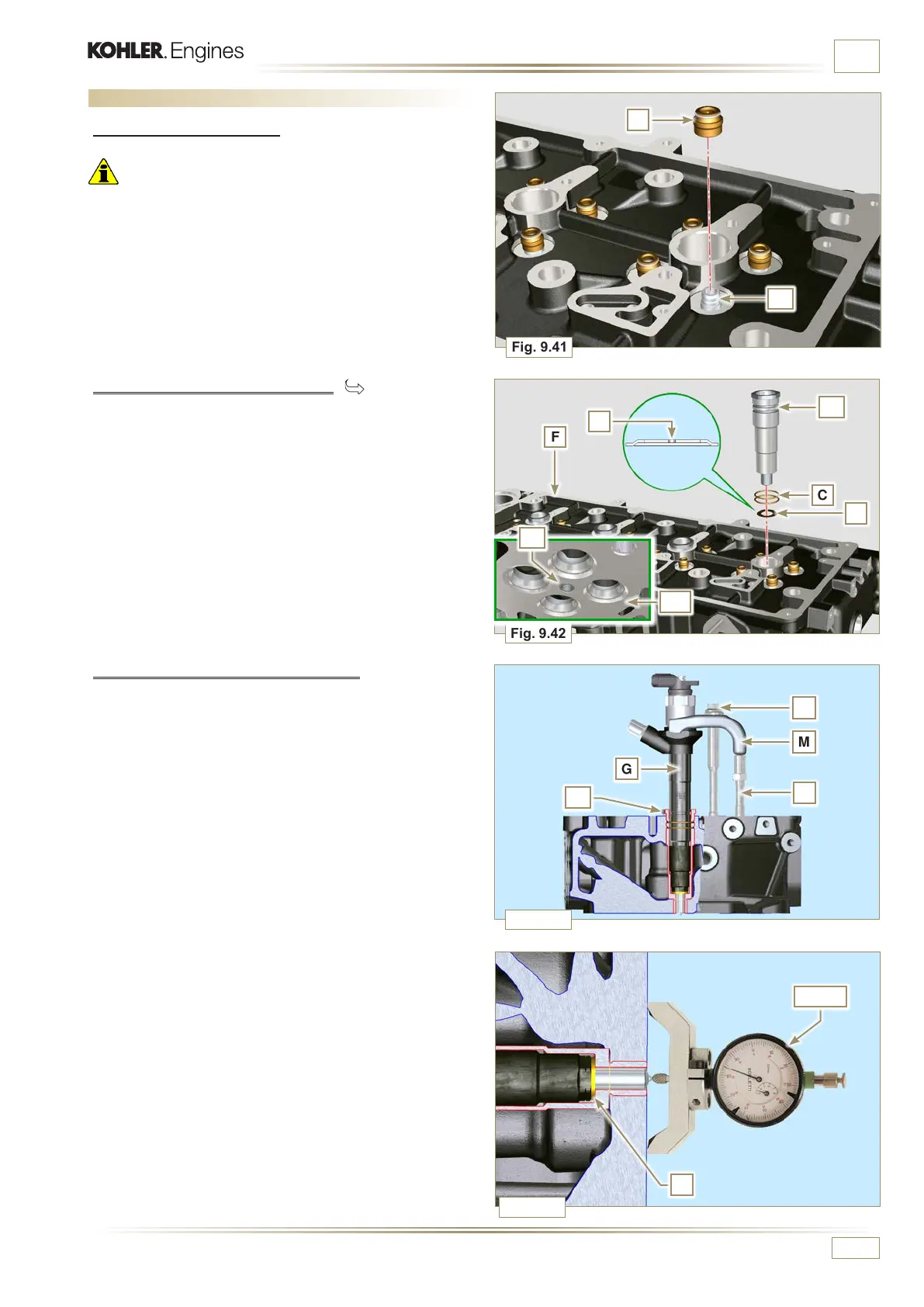
9.7.2 Electronic injector sleeves ( )
1 - Insert the seals C in the seats of the sleeve D.
2 - Insert the seal E with the convex side facing upward at the
base of the sleeve D.
3 - Lubricate the gaskets C.
4 - Insert and carefully screw the sleeve D into the seat of the
head F.
NOTE: The sleeve D must not protrude above the surface of
the head BF.
5 - Clamp the sleeve D (tightening torque at 30 Nm).
9.7.3 Electronic injectors projection
1 - Insert the electronic injector G inside the sleeve H.
2 - Mount the rocker arm pin fixing screw L up to the stop.
3 - Mount the electronic injector fixing bracket M and secure it
with the screw N, without performing the calibration.
4 - Check, using ST_03 tool (Fig. 9.44), the projection of the
injector, which must range between 1.68 ÷ 2.42 mm.
NOTE: if the value detected does not correspond, replace
gasket Q with a different thickness

 Loading...


