9
142
_07
Fig. 9.48
AX
AW
AW
F
Fig. 9.47
AJ
AJ
X
AK
S
Fig. 9.45
X
Y
F
S
F
Fig. 9.46
ST_07
F
ED0053029590
ASSEMBLY INFORMATION
9.7.5 Cylinder head
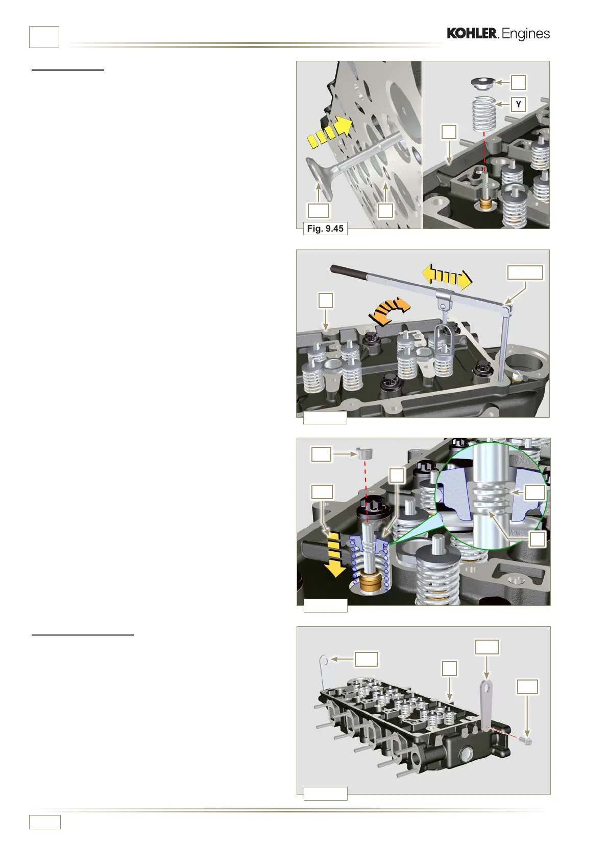
1 - Fix the eyebolts AW with the screws AX onto the head F
(tightening torque of 25 Nm).
6 -
Push the lever of the tool ST_07 downwards, in order to
lower the valve disks S in the direction of the arrow AK,
and insert the valve cotters AJ inside the disk S.
7 - Check that the valve cotters AJ are properly mounted on
the valve seats X and release the tool ST_07.
NOTE:
repeat all the steps for the relevant valves and remove
the tool ST_07.
9.7.4 Valves
1 - Pre-lubricate and insert the valves X into the head F
taking care to fit them in the original positions as per the
reference marks made in Par. 7.13.4.1.
2 - Position the spring Y on the seat of the head F.
3 - Position the disk S on the spring Y centering the valve X.
4 -
Mount the tool ST_07 on the head F fixing it on one of the
holes for securing the rocker arm cover.
NOTE:
Change the xing hole according to the position of the
valves to be tted.
5 -
Position the tool ST_07 on the valve as shown in the figure.

 Loading...


