9
143
_07
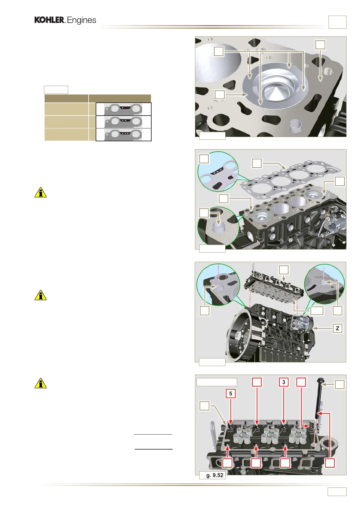
Fig. 9.52
1
2
5
4
3
6
7
8
V
Fig. 9.51
F
W
Z
JJ
Fig. 9.49
R
P
K
Fig. 9.50
K
F
J
U
T
K
ED0053029590
ASSEMBLY INFORMATION
7 - Check that the surface head W is free from impurities.
8 - Position the head F on the crankcase Z with reference to
the centering bushings J.
Important
• The fastening bolts V must be replaced every time they are
assembled.
9 - Secure the head F by tightening the screws V strictly
following the sequence indicated in the Fig. 9.52 or Fig.
9.53 and the tightening torque indicated in the Tab. 9.3.
Important
• Failure to adhere to the bolt fixing procedures may
compromise the functionality of the engine, and also may
cause damage to persons and property.
• Tighten capscrews V observing the cycles, tightening, and
subsequent rotation as indicated in Tab. 9.3.
• For engine KDI 1903 TCR: 8 screws Torx M12 x1,25 (Fig.
9.52).
• For engine KDI 2504 TCR: 10 screws Torx M12x1,25 (Fig.
9.53).
3 CYLINDERS
2 - Position the piston P at the TDC.
3
- Position the tool ST_03 on the crankcase surface of the
head and measure the piston protrusion P from head level
K in 4 diametrically opposed points R.
Repeat the operation for all pistons P and take note of the
highest average value, determining value S (Tab. 9.2).
4 -
Based on the value detected at point 3, select the relevant
gasket T as shown in the Tab. 9.2 (Fig. 9.50 detail U).
5 - Check that the crankcase surface K and the gasket T are
completely free of dirt and grit.
Important
• The head gasket must be replaced for each assembly.
6 - Position the gasket T on the surface K with reference to the
centering bushings J.
S (mm) Hole number
0.030 - 0.126 1
0.127 - 0.250 2
0.251 - 0.375 3
Tab. 9. 2

 Loading...


