9
148
_07
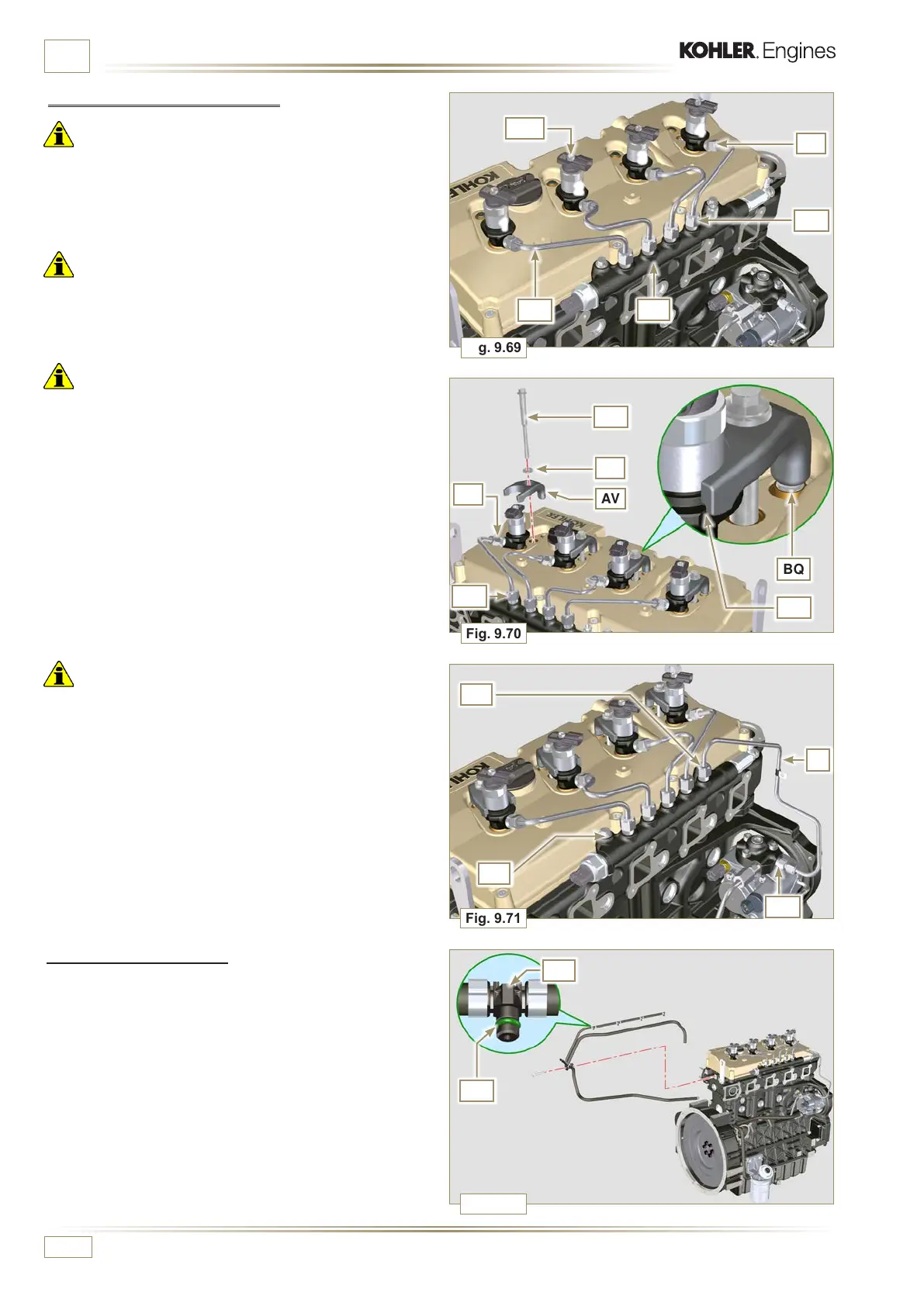
Fig. 9.70
AU
AV
AS
AJ
BQ
Fig. 9.69
AA
AQ
AM
AS
AT
2
3
4
1
Fig. 9.71
BC
BA
BB
Fig. 9.72
BD
BG
E
AT
AM
ED0053029590
ASSEMBLY INFORMATION
9.8.4 High pressure fuel pipes
Important
• A l wa y s r e p lac e t h e p ipes AQ and tube E after each assembly.
1 - Position the pipes AQ on the Common Rail AA and on the
electronic injectors AM, adjust the position of electronic
injectors AM via the fitting inlets with the pipes AQ.
Important
• Tighten the nuts AS and AT manually, without clamping them.
2 - Position the injector fastening brackets AV and the screws
AU, inserting the washer AJ.
Important
• Replace the pipes AQ (Fig. 9.69) if the screws AU do not
rotate freely.
3 - Tighten all the nuts AS (tightening torque at 30 Nm).
4 - Tighten the nuts AT (tightening torque at 25 Nm).
5 - Make sure that the mounting brackets AV are positioned
correctly on electroinjectors BR and on fixing screws of
the rocker arm assembly AM.
6 - Tighten the fixing screws of the injector mounting bracket
(tightening torque of 20 Nm).
7 - Position the pipe E screwing the screws BA and BB.
Important
• Screw the nuts BA and BB manually without tightening them.
8 - Tighten the nut BA (tightening torque of 30 Nm).
9 - Tighten the nut BB (tightening torque of 25 Nm).
10 - Tighten the Common Rail fastening screws BC (tightening
torque of 25 Nm).
9.8.5 Fuel return pipes
1 - Check the gaskets BD on the fittings BG.
NOTE: Do not disconnect the pipes from the distributor.

 Loading...


