9
147
_07
Fig. 9.66
AB
AC
AC
AA
K
Fig. 9.65
R
N M
N
AE
Fig. 9.67
AF
AG
AD
Fig. 9.68
AH
AM
AL
AN
2
3
4
1
BQ
AL
ED0053029590
ASSEMBLY INFORMATION
2 - Insert the tube K on the fitting coming out of the filter holder
R and on the fuel inlet fitting of the injection pump M and
secure it with the clamps N.
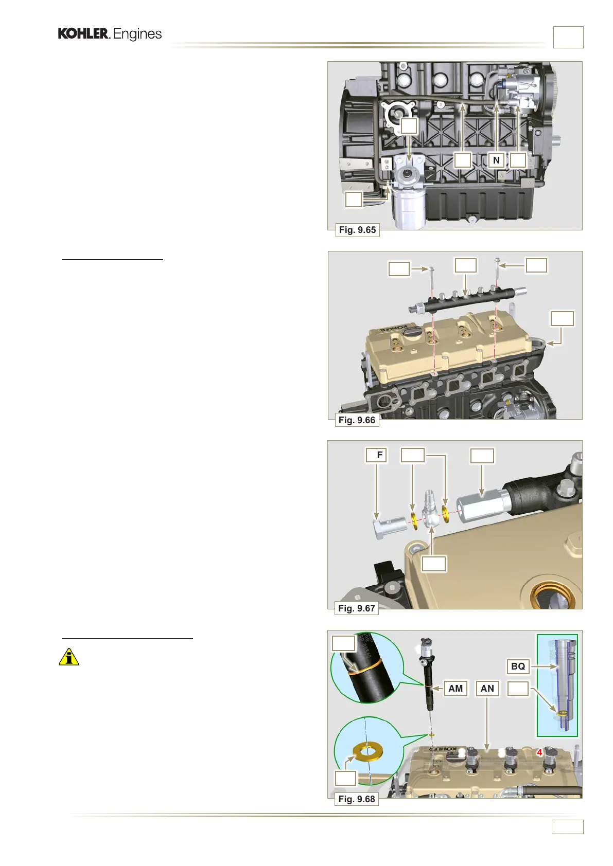
9.8.2 Common Rail
1 - Secure the rail AA on the head AB with the screws AC
(tightening torque at 10 Nm).
2 -
Fit the gaskets AD and the fitting AE on the screw AF.
3 - Tighten the parts so assembled on the Common Rail AG
(tightening torque at 15 Nm) with the entrance of union AE
facing upward.
9.8.3 Electronic injectors
Important
• Always replace and lubricate the gaskets AH and AL of
the electronic injectors AM with fuel, every time they are
assembled.
• Pay attention when repositioning the electronic injectors,
using the marks as described in Par. 7.10.5.
• If a new (or different) electronic injector is fitted on the engine,
you are required to prepare tool ST_01.
1 -
Insert the gasket AL inside the injector sleeve BQ.
2 -
Insert the electronic injectors AM inside the rocker arm
cover AN and orientate them as per Fig. 9.68.

 Loading...


