9
146
_07
S
Fig. 9.64
T
R
Fig. 9.63
1 3 75
8 4 2 6
Fig. 9.61
BF
BG
BM
F
BN
BL
Fig. 9.62
1 35
4 2 6
ST_17
BP = -90°
Fig. 9.60a
BQ
Fig. 9.60b
ED0053029590
ASSEMBLY INFORMATION
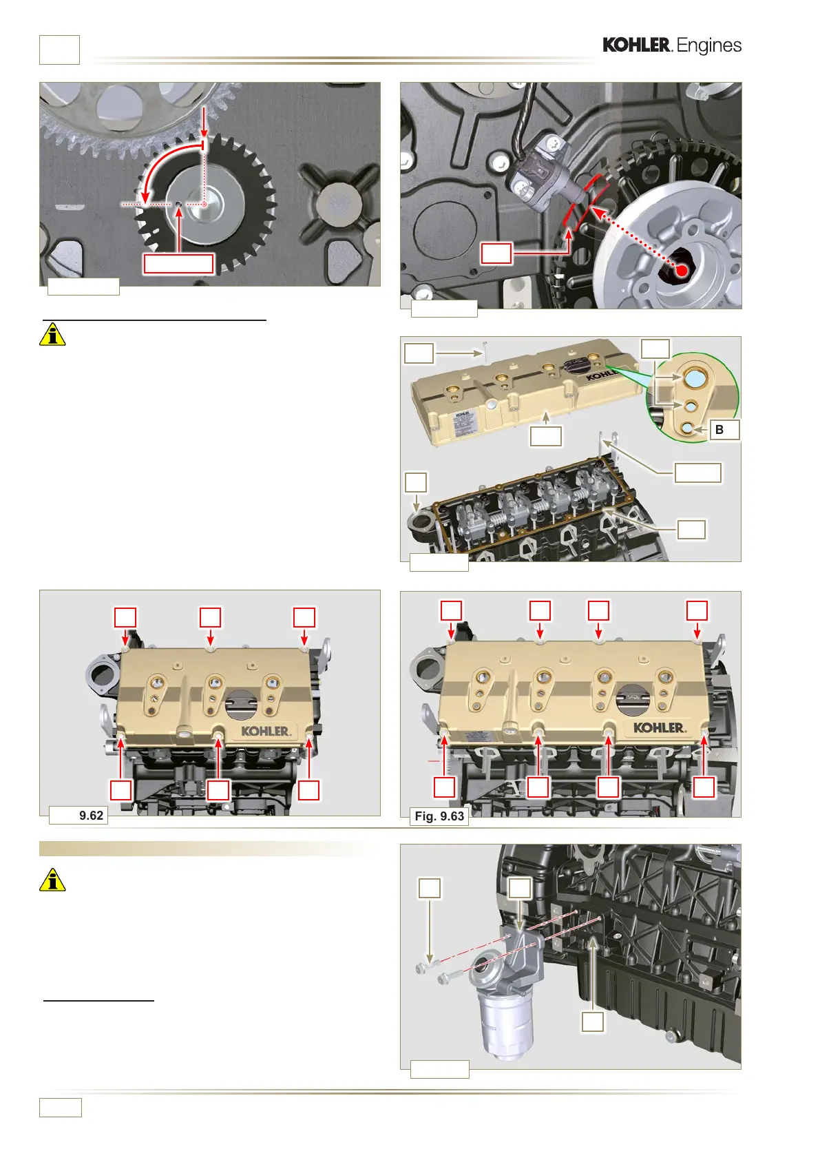
9.8.1 Fuel lter
1 - Secure the fuel filter holder R with the screws S on the
crankcase T (tightening torque of 25 Nm).
NOTE:
For the assembly of the fuel cartridge, refer to operations
4 and 5 of Par. 6.11.2.
9.8 Fuel system assembly
Important
• Do NOT mount new or different injectors without the required
tool (Chap. 13).
• Remove the protective caps from all the components of the
fuel circuit just before assembly just before assembly (Par.
2.9.8).
9.7.9 Assembly Rocker arm cover
Important
• Replace gasket BF, BL and BM with each assembly (ST_11
- ST_12).
• Observe the order of tightening illustrated in Fig. 9.62 - 9.63.
1 - Position tool ST_17 onto the head in correspondence with
the two fastening holes 5 and 6.
2 -
Position gasket BF on cylinder head F using tool ST_17 as
a guide.
3 -
With vaseline lubricate the gaskets BL in the upper part,
and the gaskets BM in the lower part.
4 -
Attach the rocker arm cover BN on the head F with the
screw BG (tightening torque to 10 Nm).

 Loading...


