9
145
_07
Fig. 9.59
BB
F
BC
BD
BB
BE
Fig. 9.60
12 3
4
AC AA
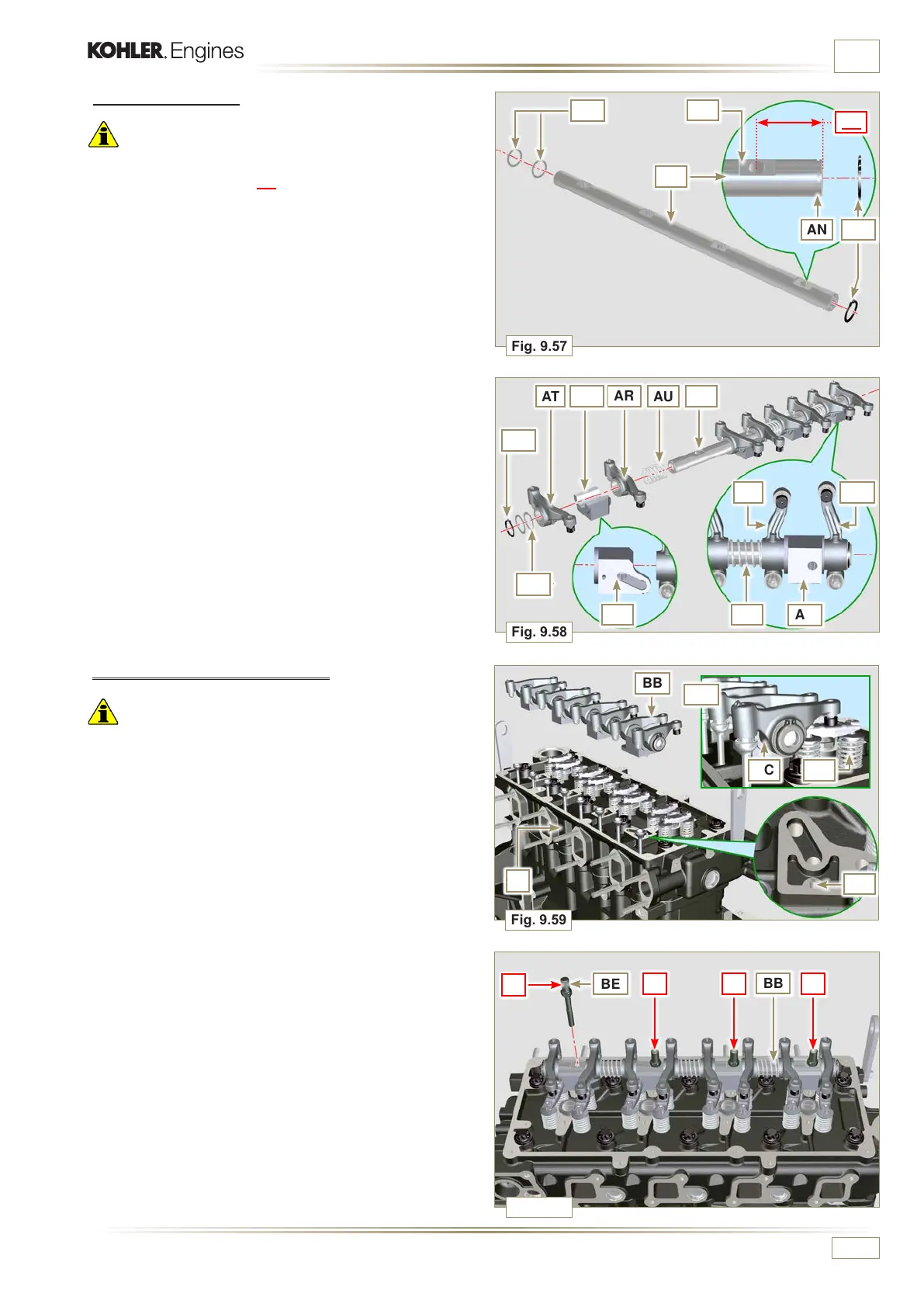
Fig. 9.57
AN
AP
AQ
AL
AH
Fig. 9.58
AR
AT
AU
AS
AUAV
AH
AR
AT
AS
AQ
AM
AM
ED0053029590
ASSEMBLY INFORMATION
9.7.8 Rocker arm pin assembly
Important
• Position the rocker arm pin assembly BB on a level to align
all the support surfaces.
• Check that the pistons are positioned half way between the
TDC and BDC. Rotate the crankshaft 90° counterclockwise
with regard to the 1
st
cylinder TDC, positioning the crankshaft
pin BP as shown in Fig 9.60a. If the crankshaft pulley and
the timing gear cover have not been removed, rotate the
crankshaft positioning the reference BQ located on the target
wheel in correspondence of the speed sensor, as shown in
Fig. 9.60b.
1 -
Position the rocker arm pin assembly BB on the head
F, respecting the plug BC on the head using the holder
indicated AV.
2 -
Check the correct positioning of all the rocker arms and the
u-bolt control valves (detail BD).
House the tappet in the seat of the rocker arms control rod.
3 - Secure the rocker arm pin BB tightening the screws
BE (tightening torque to 25 Nm). Adhere to the screw
tightening sequence BE as shown in Fig. 9.60.
9.7.7 Rocker arms
Important
• To correctly position the rocker arms, turn the rocker arm pin
AH with the lower height AL towards the timing system side
as in Fig.9.57.
• The discharge rocker arm AT is shorter than the suction arm
AR.
1 -
Fit the lock ring AM into the seat AN of the rocker arm pin
AH.
2 -
Position the pin AH with the screw support surface AP
facing upwards and insert the 2 shoulder rings AQ.
3 -
Insert in sequence the suction rocker arm AR, the holder
AS and the discharge rocker arm AT in the pin AH.
4 -
Insert the spring AU in the pin AH.
5 -
Repeat points 3, 4 for all the rocker arms.
NOTE:
The holder AV must be tted with the last pair of rocker
arms towards the ywheel.
6 - Insert 2 shoulder rings AQ and the lock ring AN to lock all
the components inserted in the pin AH.
NOTE:
The spring AU ensures that the supports AS and AV
are kept in place .

 Loading...


