9
149
_07
B
A
C
Fig. 9.75
E
F
C
G
H
Fig. 9.76
Fig. 9.74
Fig. 9.73
BE
BC
BF
BH
AM
CLICK
BL
BN
BM
BP
D
ST_18
ED0053029590
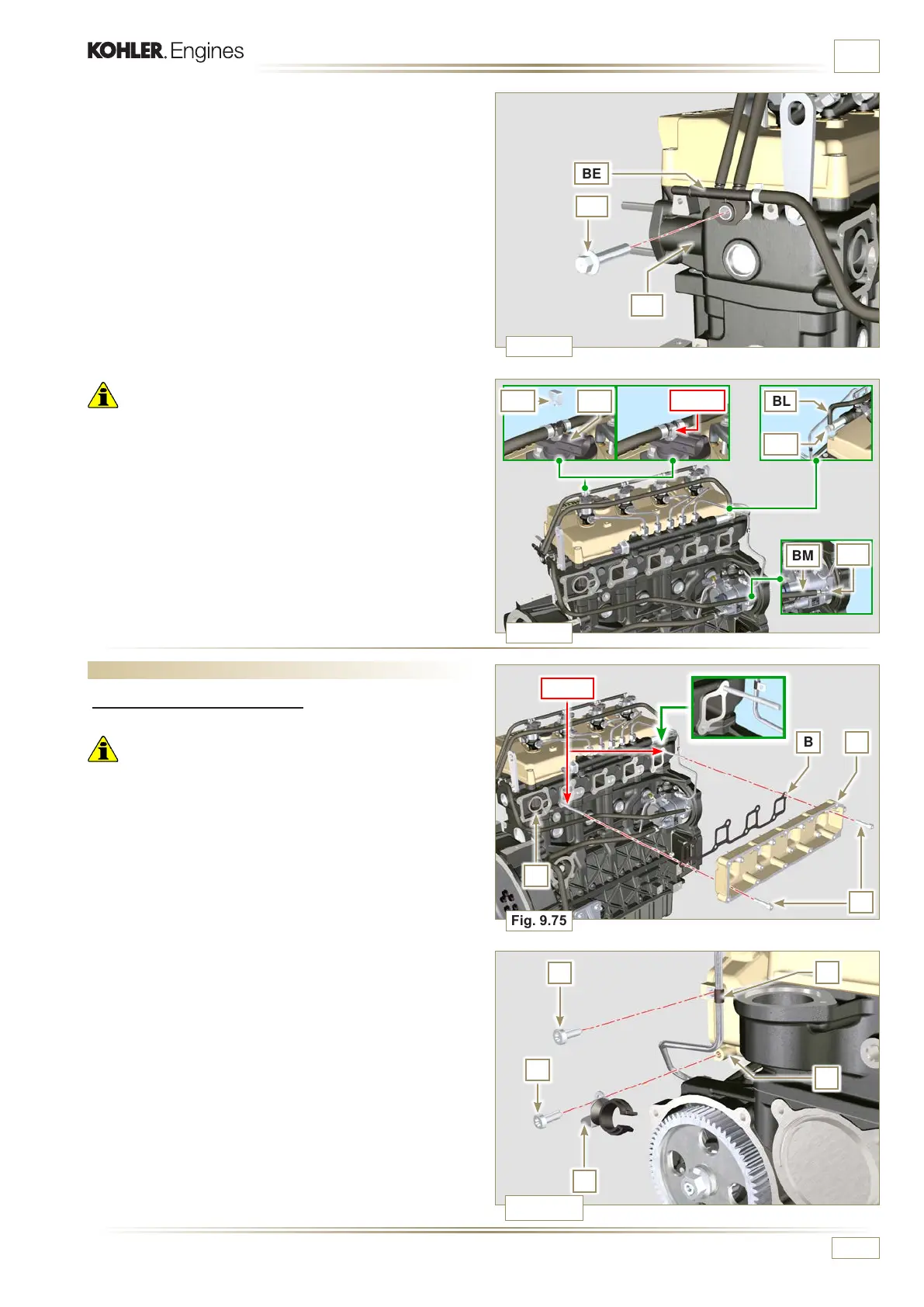
ASSEMBLY INFORMATION
Important
• Pipes of a "BASE CONFIGURATION" (refer to Par. 1.5)
engine are shown.
Other return pipes can be missing or different.
• The pipes can vary in quantity, size and dimensions depending
on the engine version.
2 -
Position the return pipes and fitting the distributor BE with
the screw BC on the head BF (Fig. 9.72 - tightening torque
of 10 Nm).
3
- Mount the fittings BG (Fig. 9.74) on the injectors AM and
lock them with the clips BH.
4 - Insert the pipe BL on the fitting BN.
5 - Insert the pipe BM on the fitting BP.
9.9 - Intake manifold assembly
9.9.1 Internal half-manifold
Important
• Check that the contact surfaces between the semi-collector
C and the head D are free from impurities.
1 - Insert the special tool ST_18 into indicated point.
2 - Insert the screws A and the gasket B on the semi-collector
C.
3 - Secure the semi-collector C with the screws A on the head D
(tightening torque of 25 Nm).
4 - Tighten the clamp E with the screw F on the semi-collector
C (tightening torque of 10 Nm - ST_06).
5 - Tighten the screw G and the holder H on the semi-collector
C (tightening torque of 10 Nm - ST_06).

 Loading...


