9
150
_07
E
Fig. 9.80
A
BC
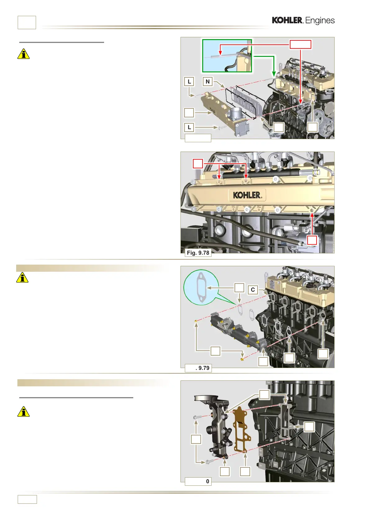
Fig. 9.78
Q
Q
D
L
L
N
P
C
Fig. 9.77
M
Fig. 9.79
A
F
C
E
B
D
ST_18
ED0053029590
ASSEMBLY INFORMATION
9.10 Exhaust manifold assembly
Important
• Replace the self-locking nuts B and the metal gaskets D
between the manifold and the cylinder head every time they
are disassembled.
• In the event of mounting the studs C, fix (25 Nm tightening
torque) with Loctite 2701 on the thread.
1 -
Check that the contact surfaces F are free from impurities.
2 -
Insert the gaskets D and E on the studs C.
3 -
Position the manifold A on the studs C.
4 -
Fix the manifold A on the cylinder head by tightening the
self-locking nuts B (tightening torque of 25 Nm).
9.11 Assembly lubrication circuit
9.11.1 Assembly oil mist separator unit
Important
• Always replace the gasket B after each assembly.
• Always carefully inspect the condition of the pipes, and
replace them if there is any doubt regarding the integrity of
their seal.
1 - Check that the contact surfaces A are free from impurities.
2 -
Mount the gasket B on the holder C.
3 - Fix the separator body holder C on the crankcase E with the
screws D (tightening torque of 12 Nm) fitting the gasket B.
9.9.2 External half-manifold
Important
• Check that the contact surfaces between the two semi
collectors C and D are free from impurities.
1 - Fit the screws L on the semi-collector M freeing the holes
Q indicated in Fig. 9.78.
2 - Mount the gaskets N on the semi-collector by interposing
the separation sheet P.
3 - Fit the semi-collector M on the semi-collector C with the
screws L (tightening torque of 22 Nm - ST_05).

 Loading...


