9
151
_07
Fig. 9.83
E
V
AB
AA
G
F
K
H
C
J
Fig. 9.81
AC
BM
BN
V
Fig. 9.84
L
L
R
T
Q
S
N
P
Fig. 9.82
ED0053029590
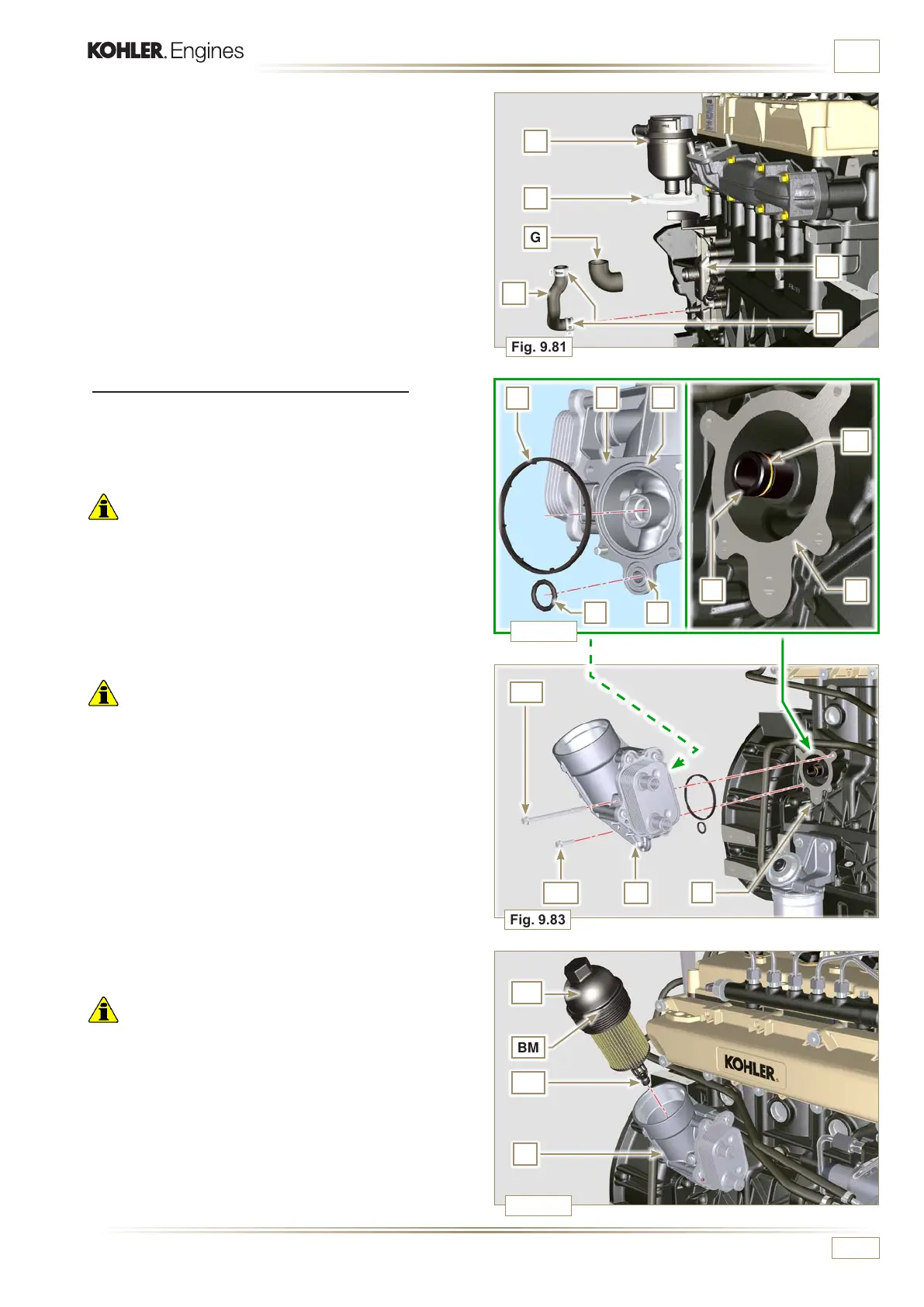
ASSEMBLY INFORMATION
9.11.2 Oil Cooler and oil lter Unit Assembly
1 - Check that the surface L on the holder V and on the
crankcase E are free from impurities.
2 - Lubricate and insert the gasket N on the fitting P.
Important
• Always replace the gaskets Q and S every time they are
disassembled.
3 - Lubricate and insert the gaskets Q and S respectively in
the seats R and T of the holder V.
4 - Secure the holder V with the screws AA and AB (tightening
torque of 10 Nm).
Important
• In the event of mounting the fitting P on the crankcase E
(tightening torque of 15 Nm with Loctite 2701 on the thread).
NOTE:
To assemble the oil cartridge refer to operations 5 and
6 of Par. 6.10.2.
Important
• Always replace the gaskets BM and BN every time they are
assembled.
5 -
Insert and tighten the cartridge-holder cover AC on the
filter holder V (tightening torque of 25 Nm).
4 -
Fit the pipes F and G on the holder C.
5 -
Insert the bleeder H attaching it to the pipes F and G.
Secure the pipe F with the clamps J.
6 -
Secure the bleeder H onto the holder C with the clamp K.

 Loading...


