9
152
_07
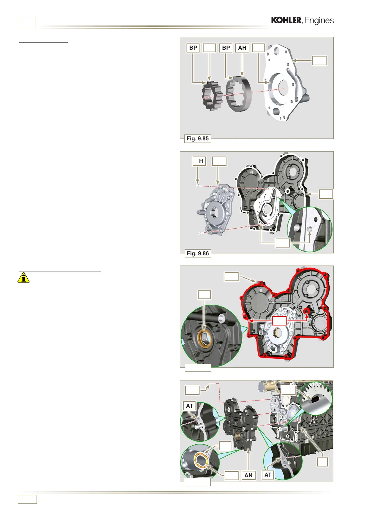
Fig. 9.85
AH AG
AM
AN
Fig. 9.86
AT
AT
E
AW
AN
AU
AV
AS
Fig. 9.88
Fig. 9.87
AQ
AN
AP
AHBPBP
AL
AG
AF
ED0053029590
ASSEMBLY INFORMATION
9.11.3 Oil pump
NOTE: Carry out the checks described in Par. 8.7 before
proceeding with the following operations.
1 - Check that all contact surfaces between AL, AH, AF, AG
and AN are free of impurities – scratches - dents.
2 - When assembling, do not use any type of gasket between
AG and AN.
3 - Thoroughly lubricate the seat of the rotors AF on the oil
pump crankcase AG and the two rotors AH and AL.
4 - Insert, inside the seat AF, the 2 rotors (in sequence) AH
and AL, respecting the reference BP as the picture (or
refer to Par. 2.10.2).
5 - Check that the 2 pins AM are inserted properly in the
crankcase timing system AN.
6 - Position the oil pump assembly AG using the pin marks
AM.
7 - Fasten the oil pump cover AG with the screws AH
(tightening torque 10 Nm).
9.11.4 Timing system carter
Important
• Always replace the gasket AU after each assembly.
• Always replace the gasket AP after each assembly (ST_14).
1 - Distribute a bead of Loctite 5188, of about 1mm thickness,
on the surfaces AQ of the crankcase AN.
2 - Make sure that the key AS (Fig. 9.88) is inserted properly
on the crankshaft and that it is facing upwards.
3 - Lubricate and insert the gasket AU in the seat of oil pump
AV.
4 - Apply the tool ST_10 onto the crankshaf.
5 - Check that the 2 pins AT (Fig. 9.88) are properly inserted
in the timing system crankcase AN.
6 -
Lubricate the gasket AP with oil and position the carter
AN on the crankcase E, using the pins AT, inserting the oil
pump AV on the crankshaft.

 Loading...


