9
153
_07
AN
BE
BF
BG
BH
BL
Fig. 9.91
Fig. 9.90
BC
1
15
10
5
14
3
12
7 8
2
13
6
9
4
11
Fig. 9.89
F
G
H
G
N
M
Fig. 9.92
BB
BD
BA
ED0053029590
ASSEMBLY INFORMATION
9.11.6 Oil pressure relief valve
1 - Lubricate the piston BE and fully insert it in the seat BF.
2 - Insert the spring BG in the piston.
Important
• Always replace the gasket BH after each assembly.
3 - Mount the gasket BH on cap BL.
4 - Tighten the cap BL on the crankcase AN (tightening torque of
50 Nm).
9.11.5 Crankcase oil ller ange Timing System
Important
• Always replace the gasket BA after each assembly.
1 - Position the gasket BA in the seat on the flange BB.
2 - Fasten the flange BB on the crankcase BC with the screws
BD (tightening torque of 8 Nm - ST_06).
7 -
Fasten capscrews AW observing the indicated clamping
sequence (tightening torque of 25 Nm).
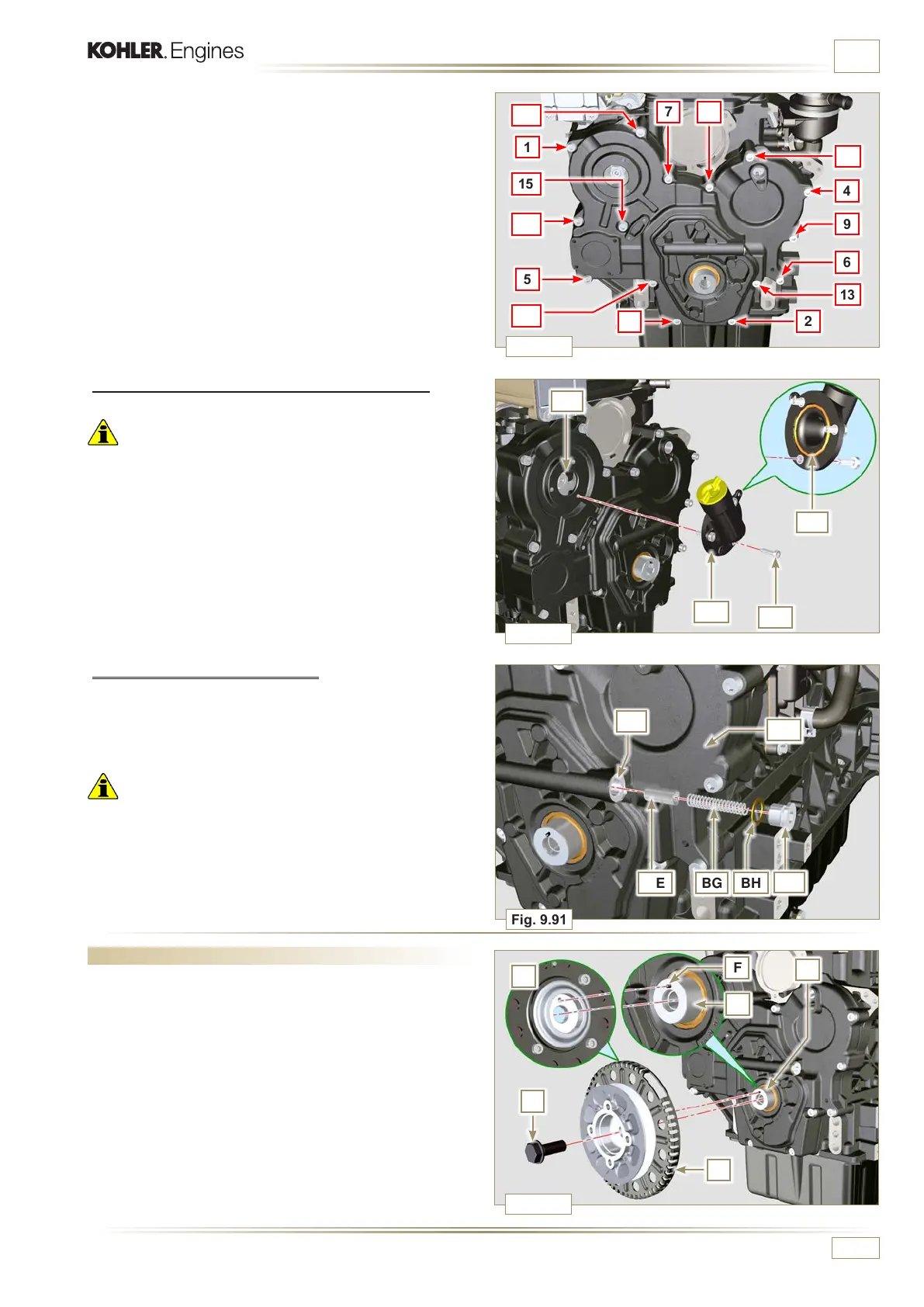
9.12 Crankshaft and phonic wheel pulley unit assembly
NOTE:
To t the phonic wheel refer to the operations in
Par. 6.6.2.
1 -
Check that the pin F is mounted properly on the crankshaft
G.
2 -
Position the pulley unit H on the crankshaft G using the pin
mark F (detail M).
3 -
Apply Molyslip grease on the screw thread N.
4 -
Fix the pulley T with the screw Z (tightening torque of 360
Nm) and remove special tool ST_34 (Fig. 9.33).

 Loading...


