9
154
_07
A
B
C
D
F
E
Fig. 9.93
LGH
Fig. 9.94
Fig. 9.96
QS YP
M
G
K
Fig. 9.95
LP
N
L
M
ED0053029590
ASSEMBLY INFORMATION
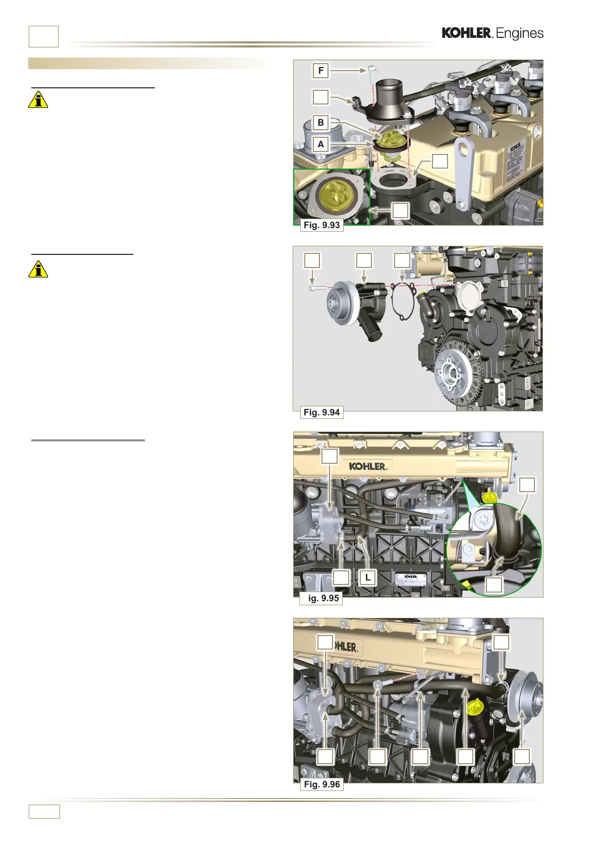
9.13.2 Coolant pump
Important
• Always replace the gasket L every time it is assembled.
1 - Fit the pump G with the screws H interposing the gasket L
(tightening torque of 25 Nm).
9.13 Coolant circuit assembly
9.13.1 Thermostatic valve
Important
• Always replace the gasket A after each assembly.
1 - Check the condition of the seal gasket A and fit it on the
thermostatic valve B.
2 - Position the thermostatic valve B in the seat on the head C
(detail D).
3 - Secure the cover E with the screws F on the head C
(tightening torque of 10 Nm).
9.13.3 Oil Cooler hoses
1 - Assemble the Oil Cooler hose behind the injection pump
and connect to Oil Cooler.
2 - Insert hose L into clamp N.
3
- Fasten hose L by means of clamp P on Oil Cooler M.
4 -
Secure the sleeve Q on Oil Cooler M and to the pump G
with the clamps K.
5 - Fasten the clamp Y with the screw S (tightening torque of
22 Nm - ST_05).

 Loading...


