9
155
_07
Q
H
S
R
P
R P
Fig. 9.99
Fig. 9.98
F
N
H
M
E L
H
G
Fig. 9.100
T U
W
Z
H
H T
V
W
D
A
C
B
Fig. 9.97
ED0053029590
ASSEMBLY INFORMATION
Important
• Remove the plastic or foam caps from the turbo compressor
before assembling.
• Replace nuts M with each assembly.
3 - Check that the contact surfaces E are free from impurities
deformations or cracks, otherwise replace exhaust
manifold L.
4 - Position the turbo-compressor H on the bolts on the
manifold L.
5 - Fasten the turbo-compressor H with the nuts M (tightening
torque of 25 Nm).
6 - Fasten the pipe G with the screws N to the turbo-compressor
H.
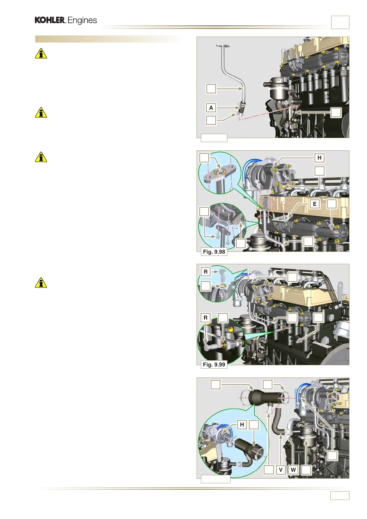
Important
• Always replace the gasket P after each assembly.
• Before assembly of the tube Q, perform the operation
described in Par. 2.19.2 - Point 2.
• Ensure that tube Q is not clogged.
7 - Fasten the fuel outlet pipe Q with the fittings R on the turbo-
compressor H and on the crankcase S (tightening torque of
15 Nm).
Insert the gaskets P between:
- Q and R;
- Q and S;
- Q and H.
8 - Insert the sleeve T on the turbo-compressor H and secure
it with the clamp U.
9 - Insert the pipe V onto the sleeve T and onto the relief valve
Z. Secure tube V with the clamps W.
9.14 Turbocharger Assembly
Important
• Before proceeding, perform the operation described in
Par. 2.19.
• Ensure that tube B is not clogged.
1 -
Fasten the connecting sleeve A to the pipe B with the
clamp C onto the flange fitting D.
Important
• Always replace the gasket F after each assembly.
2 - Lubricate and insert the gasket F into the seat of the pipe
G.

 Loading...


