9
156
_07
A
C
B
Fig. 9.101
E
D
Fig. 9.102
Fig. 9.104
L
Q
P
H
L
M
N
F G
Fig. 9.103
ED0053029590
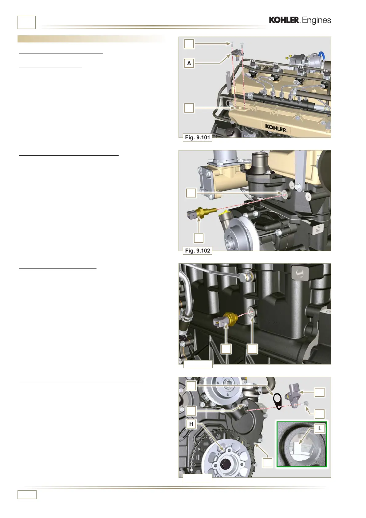
ASSEMBLY INFORMATION
9.15 Electric component assembly
9.15.1 Sensors and switches
9.15.1.1 T-MAP Sensor
1 - Fasten the sensor A with the screws B on the manifold C
(tightening torque of 10 Nm - ST_06).
9.15.1.4 Camshaft phase sensor disassembly
1 - Rotate the crankshaft H posizioning a tooth L of the phonic
wheel which is mounted on the camshaft at the center of
hole M.
2 - Carry out the steps described in points 5, 6 and 7 to insert
the correct number of spacers N.
3 - Fit the spacer N on the sensor P.
4 - Fasten the phase sensor P on distribution guard L with the
screw Q (tightening torque of 10 Nm - ST_06).
9.15.1.2 Coolant temperature sensor
1 - Secure the sensor D onto the head E (tightening torque of
20 Nm).
9.15.1.3 Oil Pressure Switch
1 - Clamp the oil pressure switch F on the crankcase G
(tightening torque at 35 Nm).

 Loading...


