9
157
_07
Fig. 9.107
Z
T
V U S
AB
AC
Fig. 9.108
AA
Fig. 9.105
X1
X2
Z1
Y1
Y2
Z2
AD
AE
AD
AE
R
V
Fig. 9.106
ED0053029590
ASSEMBLY INFORMATION
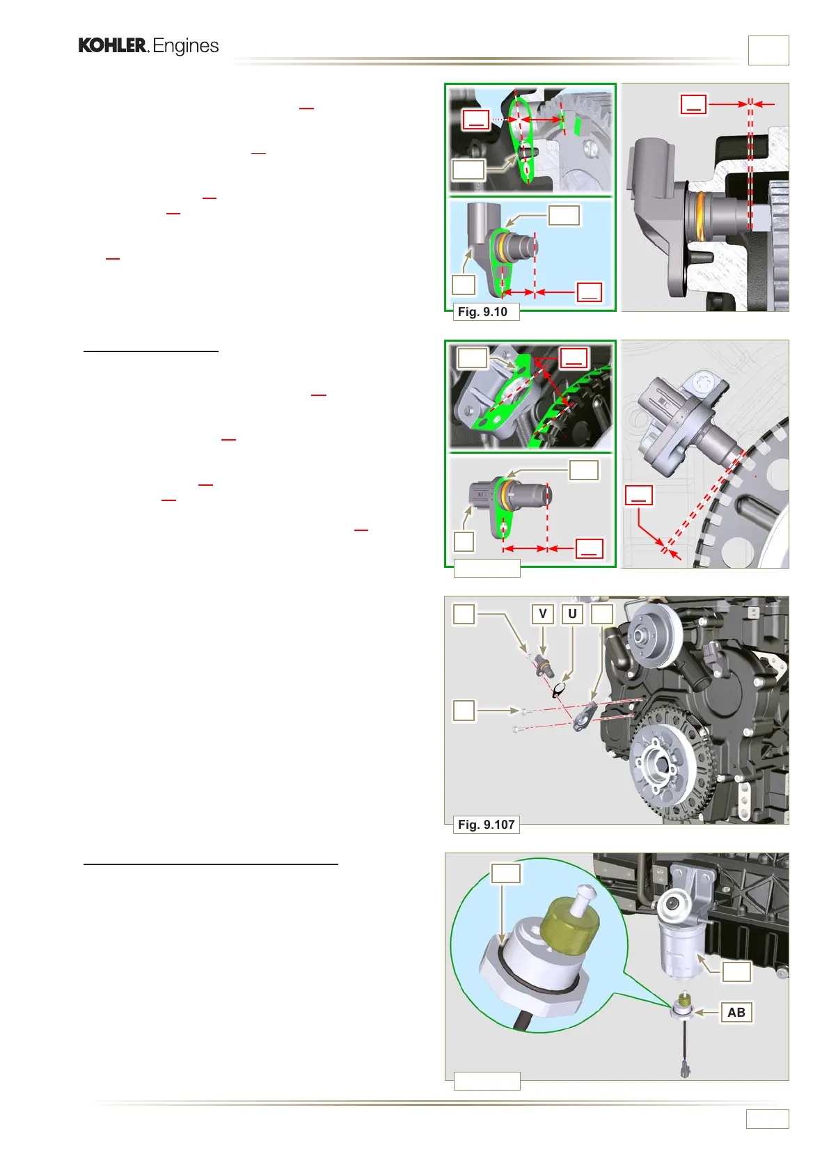
9.15.1.5 Speed sensor
1 - Measure the distance from the coupling surface AE to the
external diameter of the phonic wheel (X2).
2 - Measure the distance between the coupling surface AE and
the sensor surface V (Y2).
3 - The difference between the 2 measurements
determines
the air gap value (Z2).
The value (Z2) permitted must be a minimum of 0.2 mm and
a maximum of 1.2 mm.
Insert one or two spacers U based on the value (Z2) detected.
NOTE: The calibrated spacers U have a thickness of 0.2mm.
4 - Mount the bracket S with the screws T (tightening torque at
10 Nm - ST_06).
5 - Insert the shim U on the sensor V.
6 - Clamp the sensor V on the bracket S with the screw Z
(tightening torque at 10 Nm - ST_06).
5 - Measure the distance from the coupling surface AD to the
tooth surface on the phonic wheel (X1).
6
- Measure the distance between the coupling surface AD
and the sensor surface R (Y1).
7 - The difference between the 2 measurements determines
the air gap value (Z1).
The value (Z1) permitted must be a minimum of 0.2 mm
and a maximum of 1.2 mm.
Insert one or two spacers N (Fig. 9.104) based on the value
(Z1) detected.
NOTE:
The calibrated spacers N have a thickness of 0.2mm.
9.15.1.6 Fuel lter water detection sensor
1 - Lubricate and insert the gasket AA on the fitting AB.
2 - Tighten the sensor AB onto the cartridge AC (tightening
torque of 5 Nm).

 Loading...


