9
159
_07
BW
C1 S1
BV
BT
BU
Fig. 9.114
C2 C3
S3 H1
DA
S2
Fig. 9.115
C5
C4
S5 S4
Fig. 9.116
Fig. 9.113
BQ
BR
BS
ED0053029590
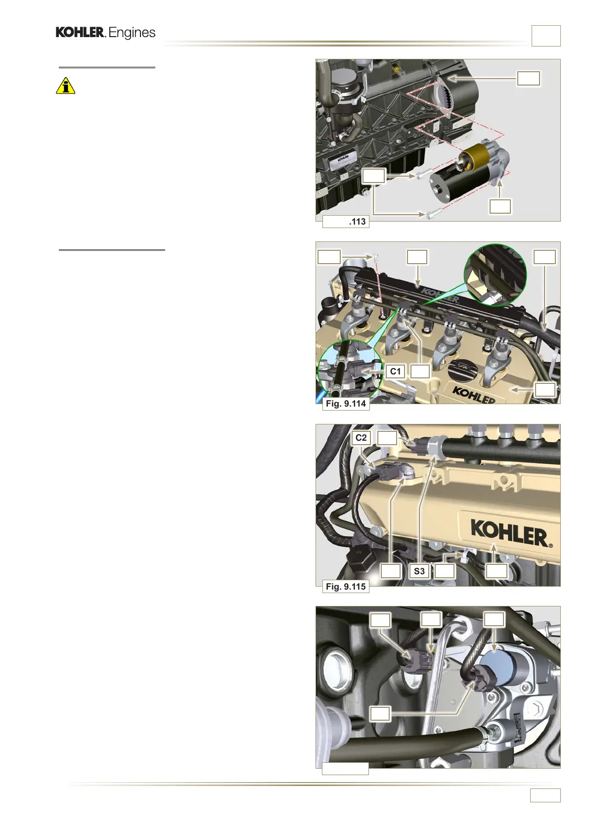
ASSEMBLY INFORMATION
4 - Fit the connector C2 on the sensor S2.
5 - Fit the connector C3 on the sensor S3.
6 - Insert the clamp H1 on the collector DA.
7 -
Insert the connector C4 on the fuel intake valve S4.
8 - Insert the connector C5 on fuel temperature sensor S5.
9.15.4 Electric cabling
1 - Position the cable holder BT together with the cabling BU
on the rocker cap BV.
2 - Mount the connectors C1 on the electronic injectors S1.
3 - Screw the wiring holder BT on the rocker cap BV with the
screws BW (tightening torque of 10 Nm - ST_06).
9.15.3 Starter Motor
Important
• Remove the ST_34 tool if it remains in position on the engine.
1 - Fit the engine BQ with the screws BR on to the flange bell
BS (tightening torque of 45 Nm).

 Loading...


