9
160
_07
BAD C
Fig. 9.119
B
G
F
E
Fig. 9.120
Fig. 9.118
C10
H4
S11
S10
S9C9
DD
C11
Fig. 9.117
C6
C8
H2
H3
DC
C7
S6
DB
S8
C8
S7
ED0053029590
ASSEMBLY INFORMATION
13 - Fit the connector C9 on switch S9.
14 - Insert the terminal C10 on the engine S10.
15 - Insert the connector C11 on the alternator cable S11.
16 -
Insert the clamp H4 on the vent holder DD.
9
- Fit the connector C6 on the sensor S6.
10
- Fit the connector C7 on the sensor S7.
11 - Insert the clamps H2 on the thermostat cover DB and H3
on the lateral oil intake flange DC.
12 - Fit the connector C8 on the sensor S8.
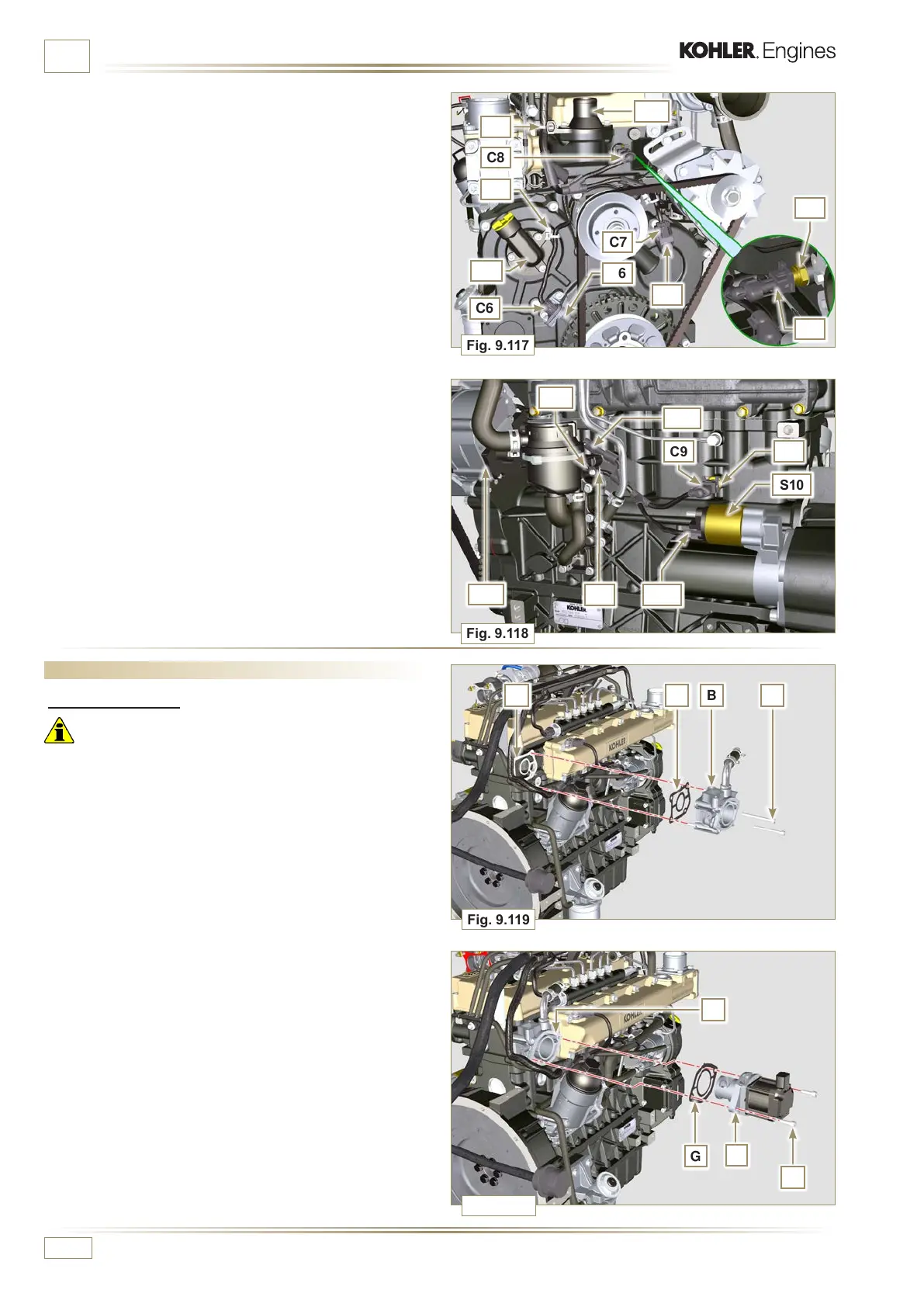
9.16 EGR Circuit Assembly
9.16.1 EGR valve
Important
• Check that the contact surfaces between flange B and the
head D are free from impurities.
• Always replace the gasket A after each assembly.
1 - Mount the gasket A on the flange B.
2 - Secure the flange B with the screws C on the head D
(tightening torque of 10 Nm).
3 -
Insert the screws E into the holder F.
4 - Position the gasket G in correspondence with the screws E
on the holder F.
5 - Secure the EGR valve holder F with the screws E on the
flange B (tightening torque of 10 Nm).

 Loading...


