9
161
_07
M
AA
AB
U
T
W
V
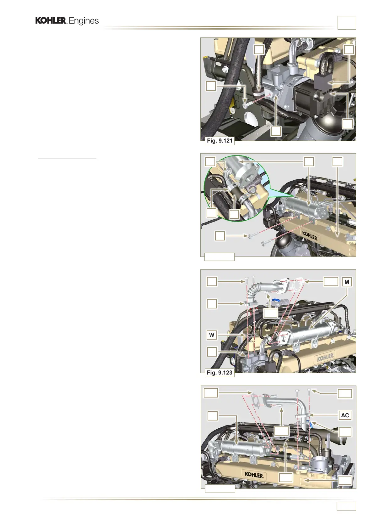
Fig. 9.123
AE
AC
AF
AH
Q
AG
AL
Fig. 9.124
L
K
J
B
Fig. 9.121
H
M
R
Fig. 9.122
Q
S
P
M
N
ED0053029590
ASSEMBLY INFORMATION
4 - Fasten the pipe T with the screws U on the EGR valve
unit V inserting the gasket W (tightening torque of 10 Nm -
ST_06).
5 - Fasten the pipe T with the screws AA on EGR Cooler M
inserting the gasket AB (tightening torque of 25 Nm).
6 -
Fasten the pipe AC on the intake manifold AD with the
screws AE (tightening torque of 25 Nm - ST_05) inserting
the gasket AF.
7 - Fasten the pipe AC on the EGR Cooler M with the screws
AG (tightening torque of 25 Nm) inserting the gasket AH.
8 - Fit the EGR Cooler M on the intake manifold Q with the
screws R (tightening torque of 25 Nm - ST_05 - Fig. 9.122).
9 - connect hose AL on EGR Cooler M.
9.16.2 EGR Cooler
1 - Insert the fitting N of EGR Cooler M in the sleeve P of the
EGR valve unit.
2 - Position EGR Cooler M on the intake manifold Q with the
screws R (ST_05).
3 - Secure the fitting N with the clamp S to the sleeve P.
6 -
Fit the connector H on the valve L.
7 -
Tighten the clamp J with the screw K on the flange B.

 Loading...


