188
11
_07
1 4
3
2
5 6
9 8
7
10
12
14
11
13
P N
D
A
BL
C D F
Fig. 11.74
Fig. 11.75
ED0053029590
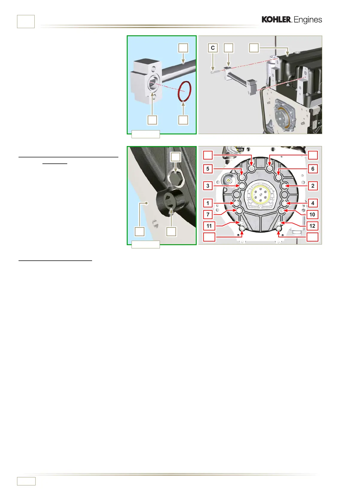
INFORMATION ABOUT OPTIONAL COMPONENTS
12 - Insert gaskets N into seats P of bypass
tube D.
13 -
F a sten bypass tube D onto oil sump F
using capscrews C (tightening torque
at 10 Nm).
11.12.5 Flange plate / housing
assembly
1 - Execute the operations described in
point 6 of Par. 11.12.4.
2 - Fasten housing or plate L by using
capscrews A and strictly following the
order shown in Fig. 11.75 (tightening
torque at 85 Nm).
3 - Fasten housing or plate L by using
capscrews B (tightening torque at 270
Nm).
11.11.6 Flywheel assembly
1 - Execute the operations described in Par. 9.5.2.

 Loading...


