189
12
_07
A
D
C
F
M
H
F
E
M
M
L
G
ED0053029590
INFORMATION ON ADJUSTMENTS
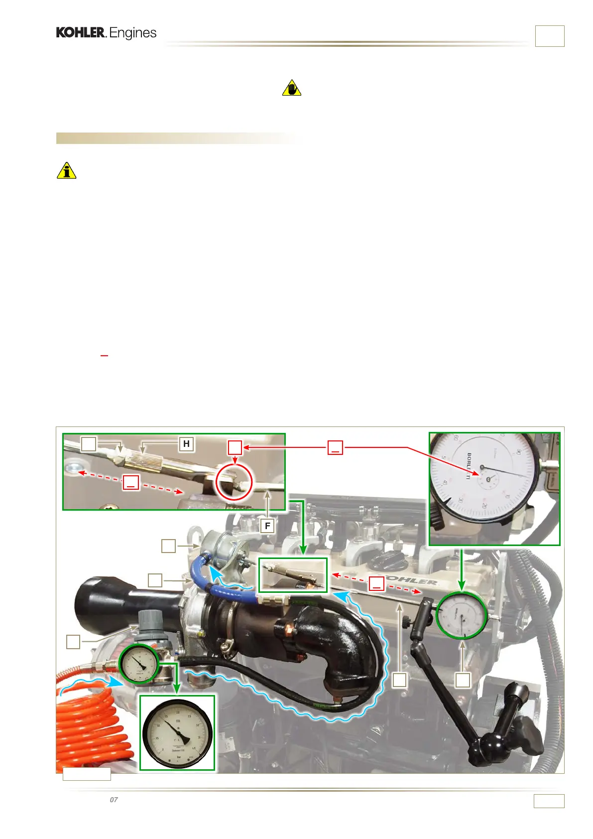
12.1 Waste Gate opening valve regulation
Important
• Regulation must not be carried out with the engine running.
During the procedure in point 5, pay special attention not to
bend rod H.
1
- Disconnect the hose A from the turbocharger.
2 -
Connect a pressure reducer C to the network of compressed
air.
The air pressure in the network must be set to 2.0 bar.
3 - Position dial gauge D in such a way that feeler F rests on
the Waste Gate rod control valve extremity H (point E).
4 -
By using reduction gear C send air to the Waste Gate
actuator control L in order to move rod H forward by 1 mm
(value
M to check on dial gauge D). Pressure read on
reduction gear C must be: 1350 mbar for engine model
KDI 2504 TCR and 1250 mbar for engine model KDI
1903TCR.
5 -
If pressure is less or more than the indicated value, proceed
as follows:
- Undo lock nut G from rod H.
- Remove the retainer cotter pin (point E) and disconnect
rod H from the Waste Gate control lever.
- Tighten (to increase) / or loosen (to decrease) pressure of
the ring nut of rod H until reaching the corrected calibration.
- Redo lock nut G.
- Reconnect rod H and assemble the cotter pin point E.
Fig. 12.1
Warning
• Before proceeding with operation, carefully read Par. 3.3.2.

 Loading...


