187
11
_07
Fig. 11.71
Fig. 11.73
Fig. 11.72
A
E
F
E
L
L
F
A
A
H
M
1
14
15
16
17
18
19
20
2
24
23
22
21
10
11
12
13
9
8
7
6 5 4 3
ED0053029590
INFORMATION ABOUT OPTIONAL COMPONENTS
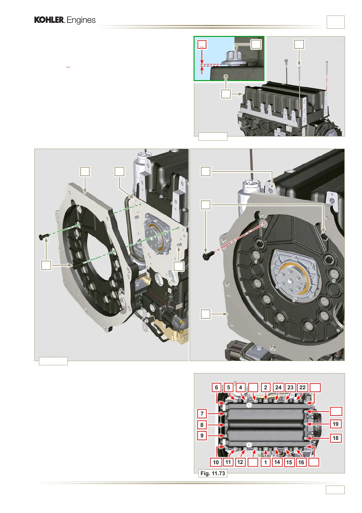
4 - Apply capscrews E into the fastening holes and use torque
at 10 Nm.
5 -
Loosen capscrews E, leaving approximately 1 mm leeway
(position A) between the neck surface of capscrews E and
oil sump F.
6 -
Place flange housing or plate L onto crankcase H,
complying with centring tap pins M.
7 - Using 2 capscrews A, fasten housing or plate L onto
crankcase H (tightening torque at 20 Nm).
8 -
Using 2 capscrews A, fasten housing or plate L onto oil
sump F (tightening torque at 20 Nm).
9 - Fasten oil sump F by tightening capscrews E and strictly
following the order shown in Fig. 11.73 (tightening torque
at 20 Nm).
10 - Loosen capscrews A and remove housing or plate L (Fig.
11.72).
11 -
F a sten oil sump F by tightening capscrews E and strictly
following the order shown in Fig. 11.73 (tightening torque
at 47 Nm).

 Loading...


