186
11
_07
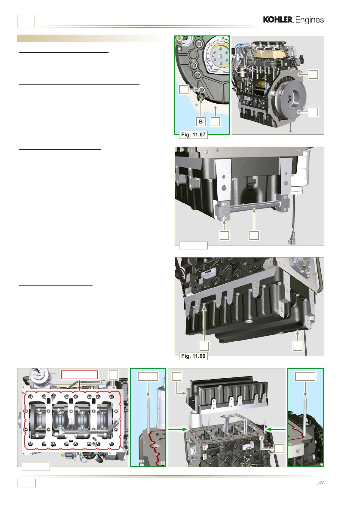
Fig. 11.67
Fig. 11.68
Fig. 11.69
Fig. 11.70
A
B
C
E
ST_18 ST_18
F
H
G
Loctite 5660
F
D
L
J
L
ED0053029590
INFORMATION ABOUT OPTIONAL COMPONENTS
11.12 Oil sump with supporting structure
11.12.1 Flywheel (J) disassembly
1 - Execute the operations described in Par. 7.12.1.
11.12.2 Plate/ange housing (L) disassembly
1 - Loosen supplementary capscrews A and B.
2 -
Execute the operations described in Par. 7.12.2.
3 - Remove housing or plate L.
11.12.3 Oil sump disassembly
1 - Execute the operations described in Par. 5.2.
2 -
Loosen capscrews C and remove bypass tube D.
3 -
Loosen capscrews E and remove oil sump F.
11.12.4 Oil sump assembly
1 - Make sure contact surfaces G of oil sump F and crankcase H
have no impurities.
2 - Apply a sealing bead of approximately 2.5 mm (Loctite 5660)
onto surface G of crankcase H.
3 - Place oil sump F onto crankcase H in correspondence with the
fastening holes (use tool ST_18).

 Loading...


