185
11
_07
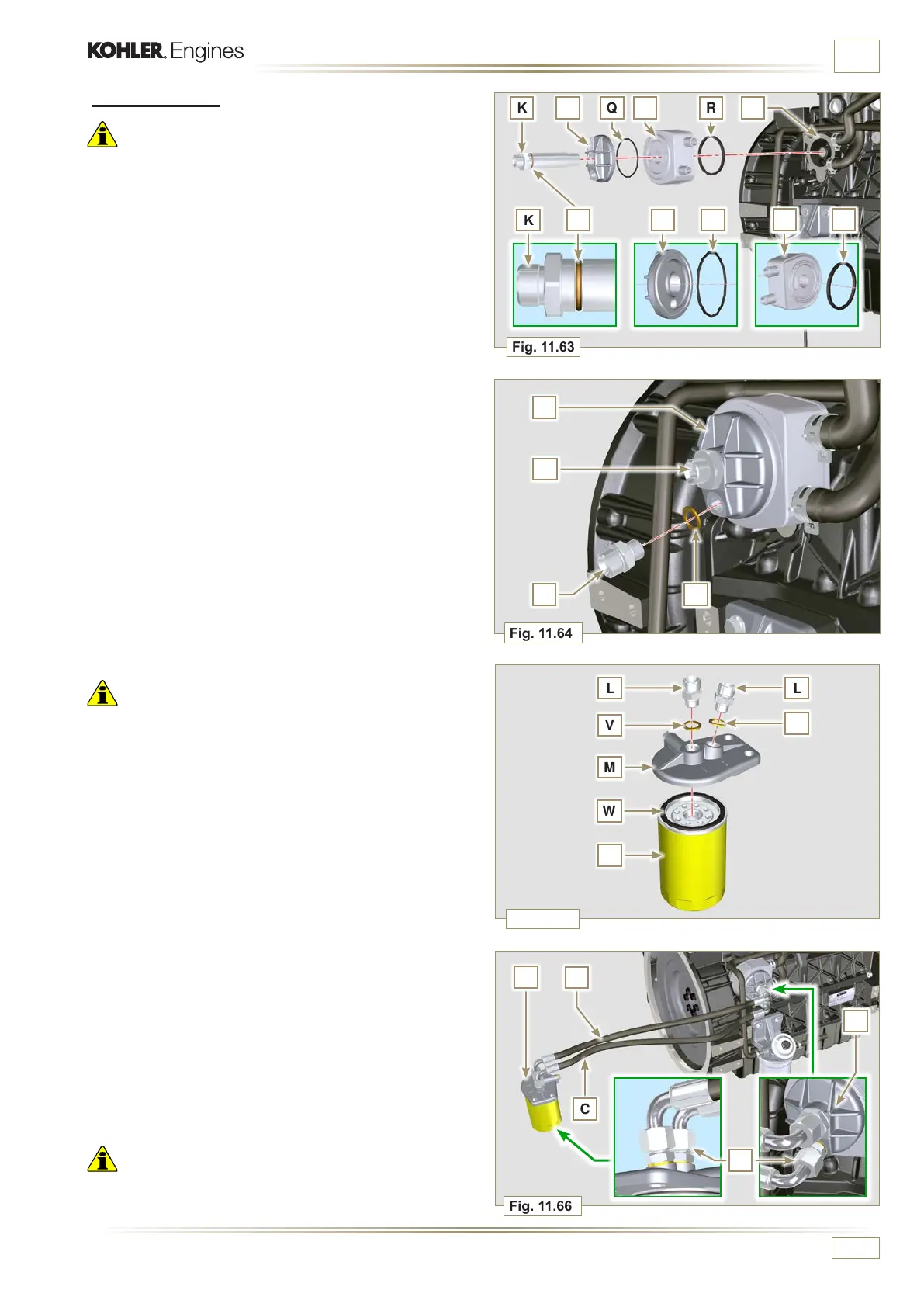
Fig. 11.65
Fig. 11.66
L
V
M
W
N
L
V
M
B
C
A
Fig. 11.64
J
H U
Fig. 11.63
K Q G R SJ
J Q
R
K
G
P
K
J
ED0053029590
INFORMATION ABOUT OPTIONAL COMPONENTS
Important
• Always replace the gaskets V after each assembly.
6 - Clamp unions L on support M inserting gasket V (tightening
torque at 40 Nm).
7 - Lubricate gasket W and clamp cartridge N on support M
(tightening torque at 20 Nm).
8 -
Connect tube B to the central union of support M and of
head J.
9 - Connect tube C to the side union of support M and of head
J.
10 - Clamp the nuts A on the head J (tightening torque at 30
Nm).
11 - Clamp the nuts A on support M (tightening torque at 35
Nm).
Important
• Check the tightening of the fittings K, H (Fig. 11.64) and L
(Fig. 11.65) (tightening torque at 40 Nm).
11.11.2 Assembly
Important
• Always replace the gaskets P, Q, R and U at each assembly.
• Lubricate the gaskets P, Q and R with oil before assembling
them.
1 -
Insert the gasket P on the seat of the fitting K.
2 -
Insert flange head J on the union K and the gasket Q in the
seat of head J.
3 -
Insert the Oil Cooler G on the union K and the gasket R in
the seat of Oil Cooler G.
4 -
Onto crankcase S apply Oil Cooler G and flange J by
means of union K (tightening torque at 25 Nm + Loctite
2701 on thread) as positioned in Fig. 11.64.
5 - Clamp union H on flange J inserting gasket U (tightening
torque at 40 Nm).

 Loading...


