184
11
_07
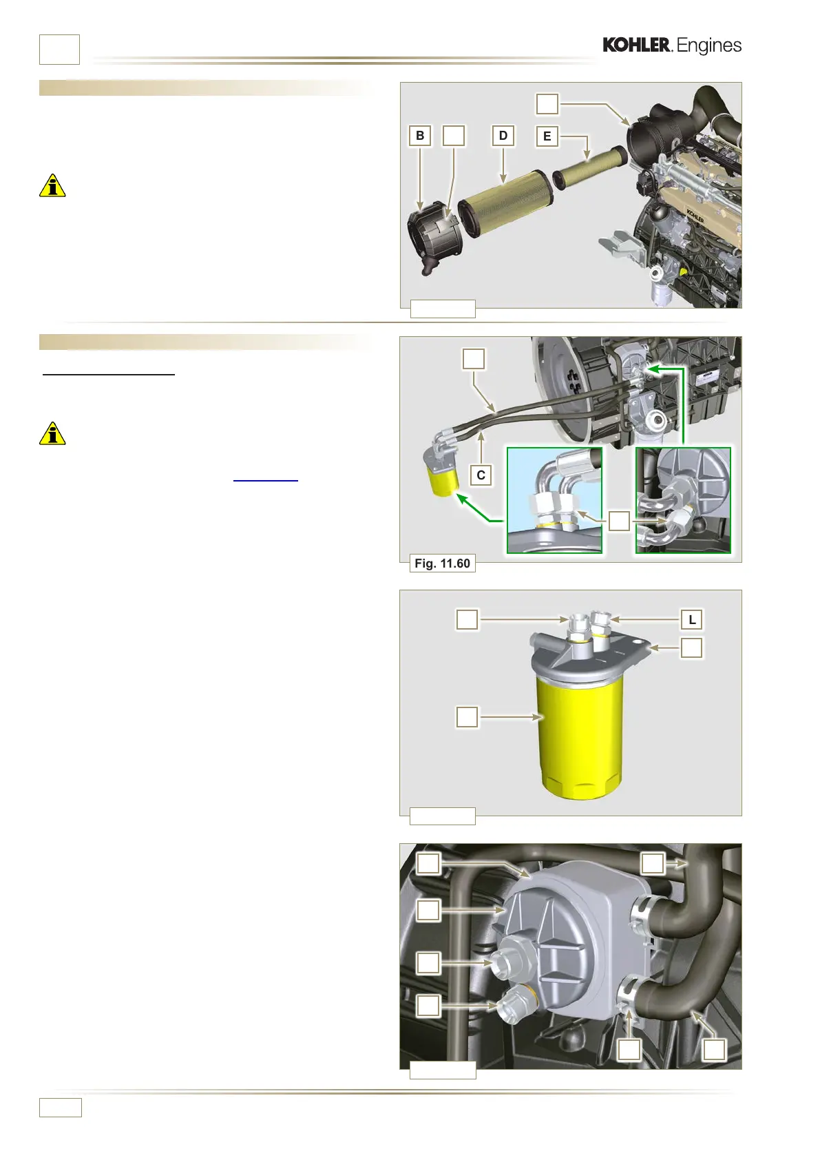
Fig. 11.60
Fig. 11.61
Fig. 11.62
B
C
F
EG
J
K
H
L
N
L
M
Fig. 11.59
B D
E
A
C
A
D
ED0053029590
INFORMATION ABOUT OPTIONAL COMPONENTS
11.11 Remote oil filter (disassembly and assembly)
11.11.1 Disassembly
1 - Perform the operations described in Par. 5.2.
Important
• For the replace the cartridge, please refer to operation n° 4
(Par. 11.11.1) and operation n° 7 (Par. 11.11.2).
• For the disassembly of the pipes B and C, lock with a tool the
fittings K, H (Fig. 11.62) and L (Fig. 11.61) in order to prevent
their lose together with the nuts A, with the consequent of oil
leakage.
2 -
Undo the nuts A and remove the hoses B and C.
3 - Unscrew the fittings L and remove the copper gaskets from
the support M.
4 - Unscrew the cartridge N with gasket from the support M.
5 -
Release the clamps D and remove the hoses E ed F from
Oil Cooler G.
6 - Unscrew and remove the fitting H with its copper gasket
from the oil filter head J.
7 - Unscrew and remove:
- the fitting K with the copper gasket;
- Oil Cooler G and the relative gaskets;
- the oil filter head J.
11.10 Air lter (cartridge replacement)
1 -
Release the two hooks A and remove the cover B from the
body C.
2 -
Remove the cartridges D and E.
Important
• The safety cartridge E (if present) must always be replaced
if it is dirty or damaged.
3 -
Insert the new cartridge E inside the new cartridge D and
both of them inside the filter body C.
4 -
Secure the cover B via the hooks A.

 Loading...


