183
11
_07
Fig. 11.57
Fig. 11.58
E
D
C
W
X
ST_15
U
F
R
Fig. 11.55
Fig. 11.56
K
P
F
ST_15
Q
ED0053029590
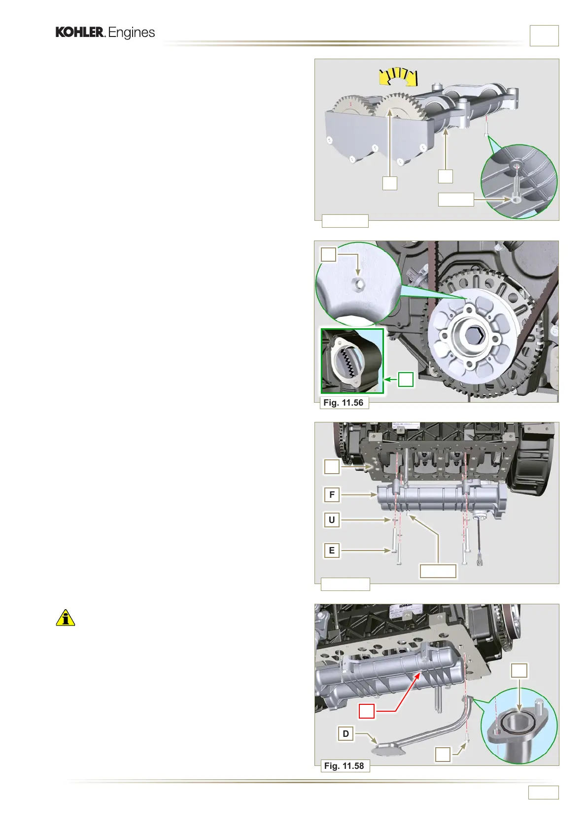
INFORMATION ABOUT OPTIONAL COMPONENTS
7 - Position the housing F on the surface of crankcase R
observing the reference bushings.
8 - Secure housing F using capscrews E inserting washers U
(tightening torque at 50 Nm).
9 - Remove the retainer screw ST_15 from the box F.
Important
• Check that the retainer capscrew ST_15 (Fig. 11.55) is not
present in point X on housing F.
• Always replace the gasket W after each assembly.
• Lubricate the gasket W with oil before assembling it.
10 - Insert the gasket W in the seat on the flange of the oil hose
D.
11 - Secure the oil intake hose D using the screws C.
12 -
Perform the operations described in Par. 9.4.3 to ass emb le
the oil sump.
5 -
Manually tighten the retainer screw ST_15 on the box F by
slightly rotating the shaft K, centring the hole on it using
the ST_15, to lock the device.
6 -
Rotate the crankshaft and clamp it on the TDC (Ref. P
upwards) using the tool ST_34 secured in place of the
starter motor (detail Q).

 Loading...


