182
11
_07
Fig. 11.51
J K
F
L
Fig. 11.52
Fig. 11.53
Fig. 11.54
J
J
G
F
H
K
K
N
F
M
V
ED0053029590
INFORMATION ABOUT OPTIONAL COMPONENTS
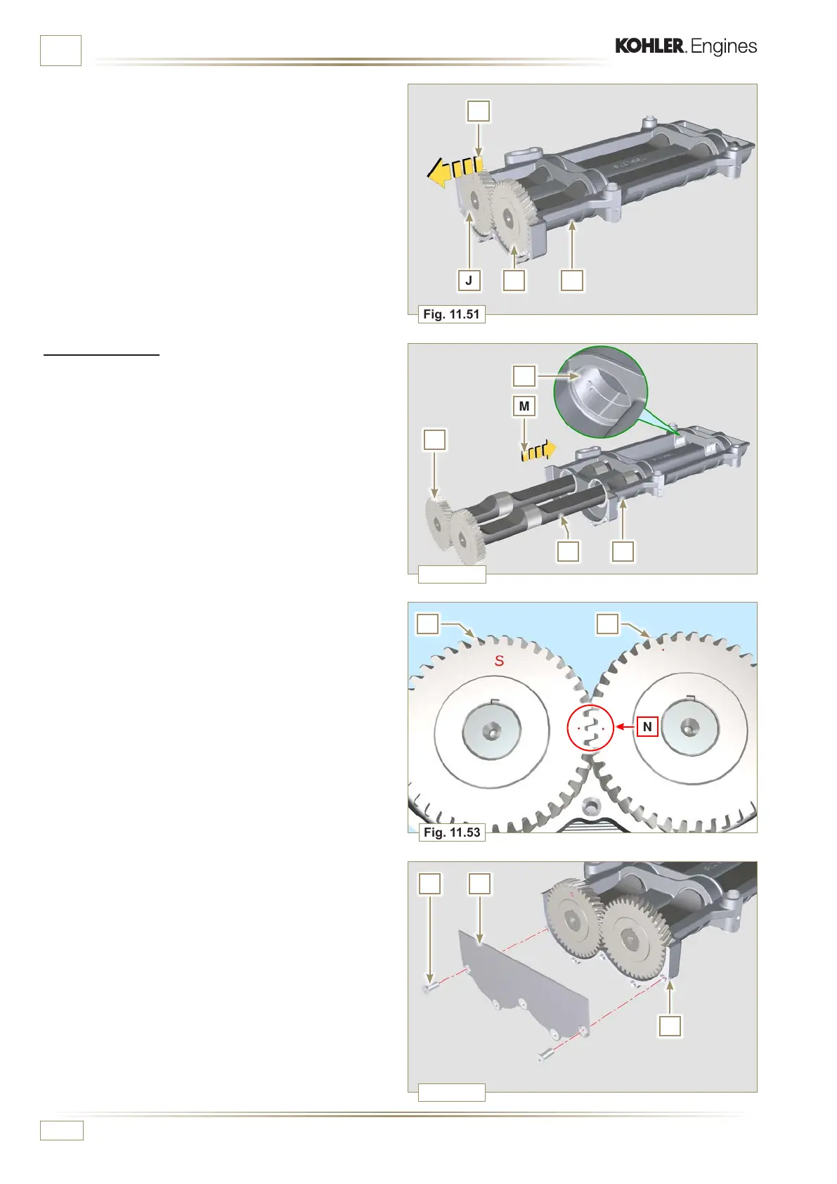
6 - Remove the shafts J and K in the direction of the arrow L
from box F.
11.9.2 Assembly
1 - Lubricate the bushings V with Molikote grease.
2 - Insert the shafts J and K inside the box F in the direction of
the arrow M.
3 -
Make sure that the shafts J and K inside the box F observe
the marks N and that the shaft J with the gear indicated by
letter "S" stamped on it is on the left with respect to the box
F.
4 -
Secure the plate H using the screws G on the box F
(tightening torque at 8 Nm).

 Loading...


