28
2
_07
5
6
7
8
9
3
Fig. 2.4
2
4
1
Fig. 2.5
9
6
8
4 3
7
2
5
1
ED0053029590
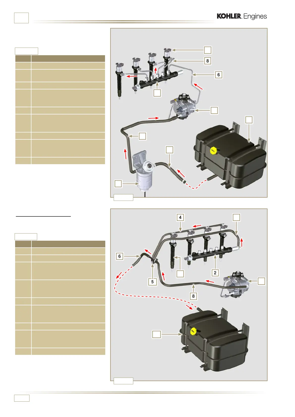
TECHNICAL INFORMATION
The fuel supply system is under low pressure
from fuel tank 1 to the high-pressure fuel
injection pump 5.
2.9.2 Fuel return circuit
The fuel return circuit is under low pressure.
Tab. 2.11
POS. DESCRIPTION
1 Electronic injectors
2 Common Rail
3
Low-pressure fuel return tube from
the Common Rail to the fuel return
distributor
4
Low-pressure fuel return tube from
the electronic injectors to the fuel
return distributor
5 Low-pressure fuel return distributor
6
Low-pressure fuel return tube from
the return distributor to the fuel
tank
7 High-pressure fuel injection pump
8
Low-pressure fuel return tube
from the injection pump to the fuel
return distributor
9 Fuel tank
Tab. 2.12
POS. DESCRIPTION
1 Fuel tank
2 Fuel pipe under low pressure from
the tank to the fuel lter
3 Fuel lter
4 Low-pressure fuel tube from the
fuel lter to the high-pressure
injection pump
5 High-pressure fuel injection pump
6 High-pressure fuel tube from the
high-pressure fuel injection pump
to the Common Rail
7 Common Rail
8
Fuel pipes under high pressure
from the Common Rail to the
electronic injectors
9 Electronic injectors
NOTE:
The representation of fuel tank is purely
indicative.
Component not necessarily supplied
by KOHLER.
NOTE:
The representation of fuel tank is purely
indicative.
Component not necessarily supplied
by KOHLER.

 Loading...


