29
2
_07
5
7
6
2
9
8
11
12
34
4
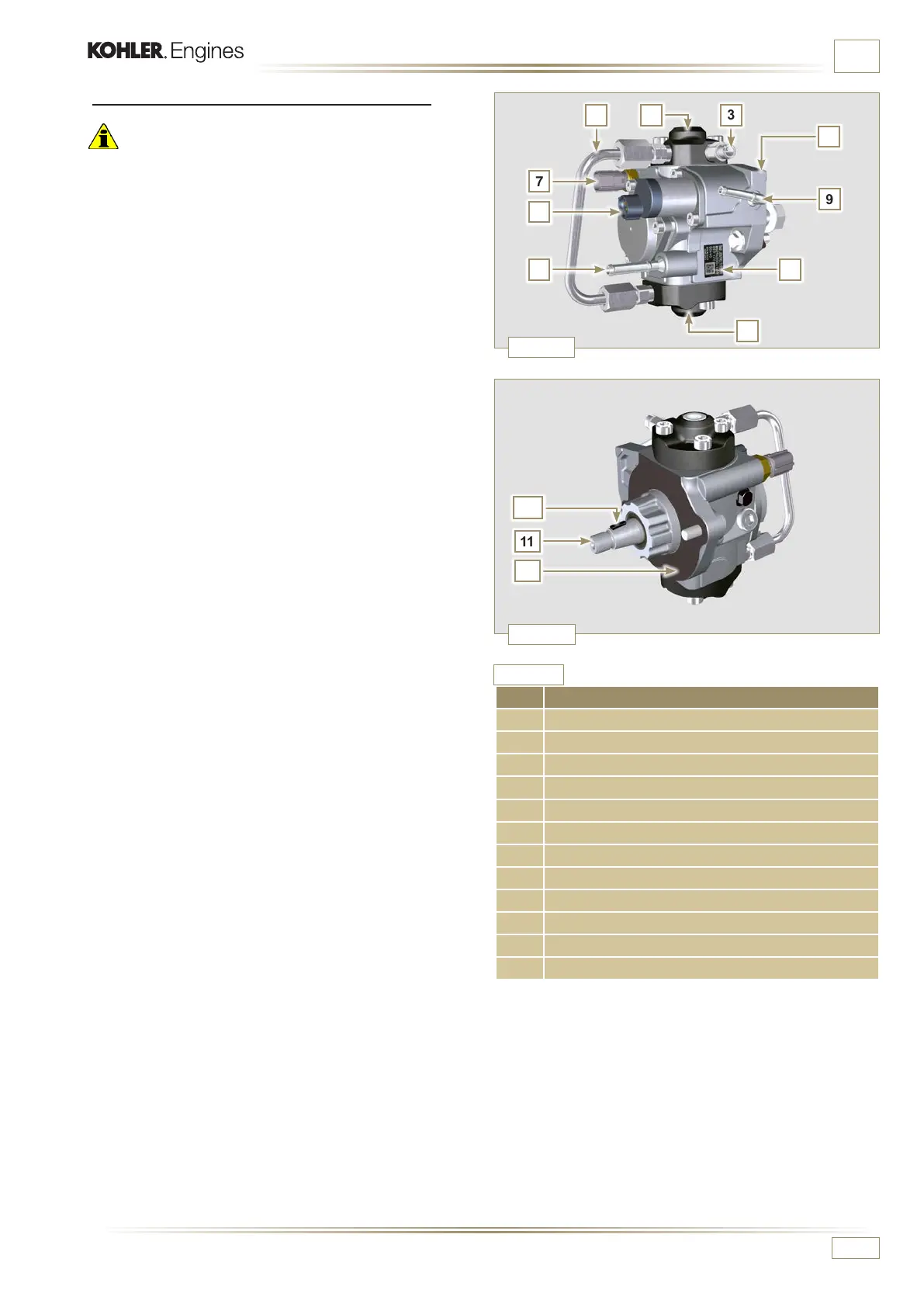
Fig. 2.6
Fig. 2.7
1
10
ED0053029590
TECHNICAL INFORMATION
2.9.3 High-pressure injection pump (2000 bar)
Important
• DO NOT use the cylinder connecting pipe (item 5) to carry
the pump during movement as this may cause damage
resulting in fuel leakag; to handle the injection pump, refer
to Par. 2.18.1.
• The injection pump CANNOT be repaired.
• Do NOT perform any maintenance on temperature sensor 7
as it is integral part of of the injection pump.
• Do NOT attempt to remove the temperature sensor 7 from
the pump. Should the sensor 7 be defective, replace the
injection pump.
• It is NOT possible to perform any maintenance on the fuel
intake regulating valve 6 as it is an integral part of the
injection pump.
• Do NOT attempt to remove the fuel intake regulating valve
6 from the injection pump. Should the valve be defective,
replace the injection pump.
NOTE: In the event of leakage from the high pressure circuit
do not intervene when the engine is running, but turn it
off and wait 5 - 10 minutes before checking the leakage.
The inlet pressure to the high pressure pump must be between
300 mbar (suction pump without electric supply) and 200 mbar
(with electric pump power) to the high pressure rail.
The high pressure pump is operated via the pump control gear
and sends high pressure fuel to the common rail.
NOTE: The supply tube (on union 8) and fuel return (on union
9), have different diameters.
Tab. 2.13
POS. COMPONENTS DESCRIPTION
1 High-pressure fuel injection pump
2 Name plate with QR code
3 Fitting for high pressure outlet to Common Rail
4 Plunger housing
5 Connection pipe plunger housing
6 Fuel intake regulating valve
7 Fuel temperature sensor
8 Fuel inlet tting
9 Fuel return tting
10 Shaft key positioning on the pump control gear
11 Pump control shaft
12 Gasket

 Loading...


