35
2
_07
1
6
4
10
11
3
6
9
8 7
8
3
4
10
11
2
5
9
12
2
1
13
14
Fig. 2.15
Fig. 2.16
ED0053029590
TECHNICAL INFORMATION
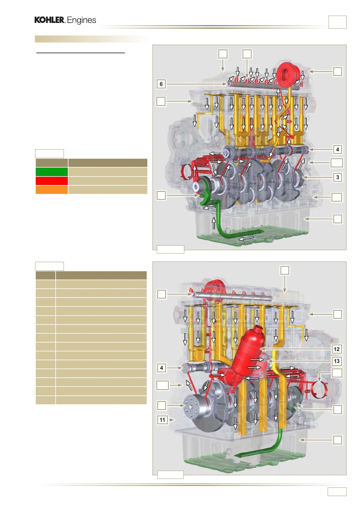
2.10 Lubrication circuit
2.10.1 Lubrication circuit diagram
The oil pump is driven by the crankshaft on the
timing system side.
In the parts in green, the oil is in intake, in the
parts in red, the oil is under pressure and in
those in yellow the oil is returning towards the
oil sump 2 (not under pressure).
Tab. 2.20
Tab. 2.19
COLOUR DESCRIPTION
Oil in intake
Oil under pressure
Oil returning to the oil sump
POS. DESCRIPTION
1 Oil pump rotors
2 Oil sump
3 Crankshaft
4 Camshaft
5 Turbocharger
6 Rocker arm pin
7 Hydraulic tappets
8 Rocker arm cover
9 Cylinder head
10 Upper crankcase
11 Lower crankcase
12 Oil lter
13 Oil Cooler
14 PTO 3
rd
/4
th
gear housing

 Loading...


