48
2
_07
A
B
E
C
D
Fig. 2.35
Fig. 2.36
G
Fig. 2.37
Fig. 2.38
F
R
ED0053029590
TECHNICAL INFORMATION
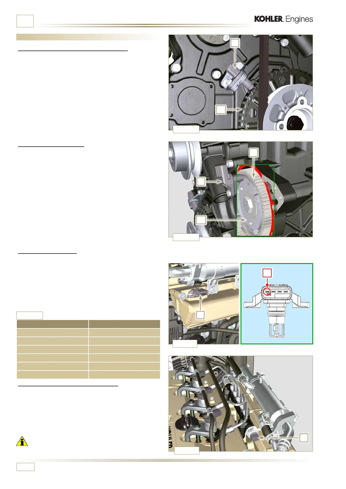
2.14 Sensors and switches
2.14.1 Revolution sensor on target wheel
Speed sensor A is situated on the timing system carter.
The sensor detects the signal from the target wheel B (60 - 2
teeth) situated on the crankshaft pulley. It sends it to the ECU
as an analogical signal.
The sensor sends and analogue signal to the ECU.
The sensor produces a 5V square wave signal having a Hall
effect while the crankshaft in rotation detects its position and
speed.
The data sent by this sensor enables the ECU to pilot fuel
anticipation injection for each piston.
For gap adjusting see Par. 9.15.1.5.
2.14.2 Camshaft sensor
The camshaft sensor C is situated on the timing system carter.
The purpose of the camshaft sensor C i s t o i d e n t i f y t h e p o si t i o n
of the camshaft control gear E with respect to the engine shaf t
and consequently the position of the pistons with respect to
the T.D.C.
The sensor produces a 5V square wave signal having a Hall
effect while the camshaft in rotation detects the phases of
the 4 strokes of the 1st cylinder. As a consequence, ECU by
means of internal calculations, also recognises the phases of
the other cylinders.
The data sent by this sensor enables the ECU to pilot fuel
anticipation injection for each piston.
For gap adjusting see Par. 9.15.1.4
2.14.3 T-MAP sensor
The T-MAP sensor F is situated on the intake manifold.
It detects the input pressure in the intake manifold by means of
electrical voltage variation and the air temperature by means
of an electrical resistor.
The sensor sends signals to the ECU, which determines the
values and modies the injection strokes.
Tab. 2.35 reports the electrical resistor values according to
the intake air temperature.
°C (°F) R (Ω)
-30 (-22) 23475 - 25945
0 (32) 5370 - 5935
25 (77) 1900 - 2100
50 (122) 772 - 854
100 (212) 177 - 195
120 (248) 107 - 119
Tab. 2.35
2.14.4 Common Rail pressure sensor
Fuel pressure sensor G assembled on the Common Rail,
detects the fuel pressure inside it by means of electrical
voltage variation.
Depending on the signal sent, ECU manages the fuel intake
valve on the injection pump and, if necessary, modies the
injection strokes.
Important
• Refer to Par. 2.9.5.
NOTE: R indicates the pin where it is possible to measure
electrical resistance.

 Loading...


